Off-Grid Solar Grounding and Bonding Explained
There’s a universal feeling of pride, and maybe a little anxiety, that comes with dreaming of or building your own off-grid solar system. You envision clean energy, independence, and quiet nights, but then the complex world of electrical codes, safety regulations, and specialized terminology starts to creep in. One area that often leaves folks scratching their heads, and frankly, feeling a bit overwhelmed, is grounding and bonding. It sounds technical, daunting even, but getting it right is absolutely crucial for the safety of your system, your property, and most importantly, your family. This comprehensive guide is here to unravel the mysteries of off-grid solar grounding and bonding, explaining what it is, why it matters so much, and how to implement it correctly so you can power your dreams with peace of mind.
Understanding Off-Grid Solar Grounding and Bonding Fundamentals
When you venture into the world of off-grid living, you become your own utility company. With that independence comes the responsibility of ensuring your power system is as safe, if not safer, than anything the grid would provide. This is where grounding and bonding step in, acting as the silent guardians of your electrical infrastructure. They're not just jargon; they're foundational safety principles.
Why Grounding is Non-Negotiable for Safety
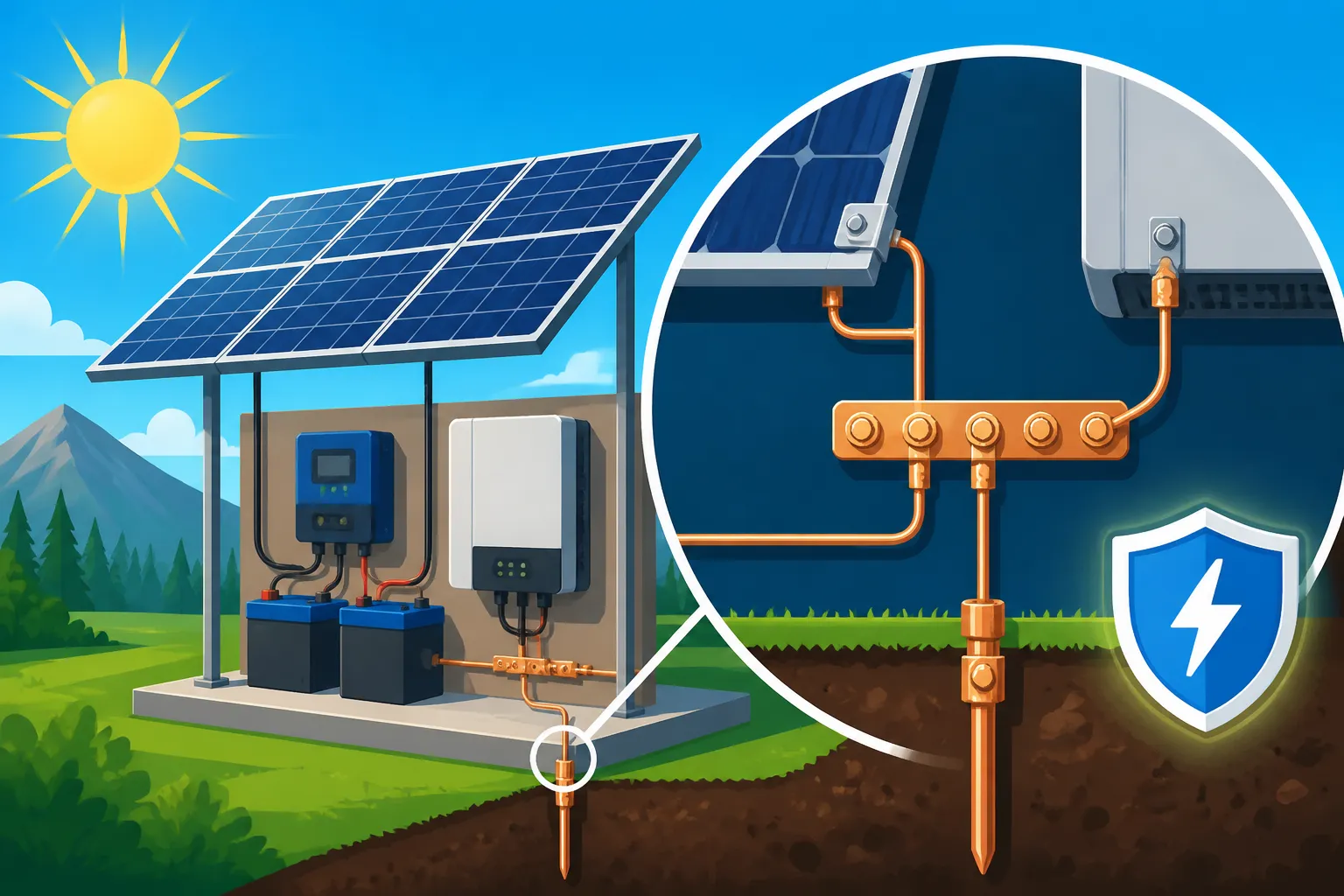
Think of grounding as creating a superhighway for electricity to safely return to the earth in case of an accident. In an off-grid solar setup, grounding means establishing a direct, low-resistance path between your electrical system and the actual ground. This path usually involves driving sturdy copper-clad steel rods deep into the earth. Why is this so critical? Well, if a fault occurs – say, a wire frays and touches the metal casing of your inverter, or a mischievous lightning bolt decides to strike near your solar panels – that excess, dangerous electrical current needs somewhere to go.
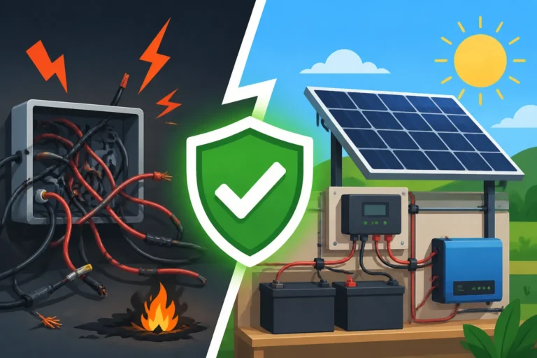
Without proper grounding, that current can build up, looking for the easiest way out. This could mean zapping you if you happen to touch a live metal component, causing extensive damage to your expensive equipment like batteries and inverters, or even worse, sparking a catastrophic fire. Grounding acts as a surge protector and a fault current diverter, ensuring that if anything goes wrong, the electricity has a clear, safe escape route, protecting both your investment and your life. It’s a fundamental part of Off-Grid Solar Safety and Grounding.
Bonding: The Unsung Hero of Electrical Continuity
While grounding gives fault current a path to earth, bonding is about connecting all the non-current-carrying metal parts of your electrical system together. Imagine every metal frame of your solar panels, the mounting rails, the inverter chassis, the battery rack, and even the metal conduit protecting your wires – bonding connects all these separate pieces into one continuous, electrically conductive system. Why go to all that trouble?
The goal of bonding is to ensure that all these exposed metallic components remain at the same electrical potential. If a hot wire accidentally touches a metal solar panel frame, for example, without bonding, that frame could become energized, waiting to deliver a nasty shock to anyone who touches it. However, if that frame is properly bonded to the rest of the system, including your main ground, the fault current will have a complete path back to its source, tripping a breaker or fuse and shutting down the dangerous condition. It’s like creating a spiderweb of safety, making sure no part of your system can accidentally become an isolated, dangerous conductor. It’s about creating an equipotential plane where everything is essentially "neutral" relative to each other, even in a fault condition.
Essential Components for a Properly Grounded and Bonded System
Building a robust off-grid solar system isn't just about collecting the best panels or the most powerful inverter; it's also about having the right supporting cast of components dedicated to safety. These elements ensure that your system can handle the unexpected without putting anyone at risk.
The Grounding Electrode System: Your System's Earth Connection
At the heart of your grounding strategy is the grounding electrode system. This is the physical connection to Mother Earth itself. The most common component here is the ground rod – typically an 8-foot-long, 5/8-inch or 3/4-inch diameter copper-clad steel rod driven completely into the ground. In many jurisdictions, especially for larger installations, you might need two ground rods spaced at least 6 feet apart to achieve sufficient earth contact. The specific number and spacing are often dictated by local electrical codes, which can vary wildly.
Connecting your main electrical system to these ground rods is the Grounding Electrode Conductor (GEC). This is a robust, bare or green insulated copper wire that runs from your main service panel or inverter's grounding lug directly to the ground rod(s). The size (gauge) of this wire is critical and depends on the size of your system's main overcurrent protection device or the largest ungrounded (hot) service conductor. For example, a common #6 AWG wire might be used for many residential off-grid systems. There are other types of grounding electrodes too, such as metal underground water pipes (with strict caveats), or a concrete-encased electrode, often called a Ufer ground, which involves rebar embedded in concrete foundations. Always check local codes and manufacturer specifications for your system components like those from Renogy to ensure you're using the correct types and sizes.
Bonding Jumpers and Equipment Grounding Conductors
Beyond the main connection to the earth, the internal continuity of your system is handled by bonding jumpers and equipment grounding conductors. Bonding jumpers are essentially short lengths of wire or metal straps used to connect different metallic parts that need to be electrically joined. For instance, you’d use a bonding jumper to connect each solar panel frame to the metal racking it sits on, and then the racking itself would be bonded to a main grounding bus. These ensure that if one part becomes energized, the charge is immediately shared with all other bonded parts, creating a unified potential.
Equipment Grounding Conductors (EGCs) are the green or bare copper wires that run alongside your "hot" and "neutral" wires inside conduit or cable assemblies. Their job is to connect the metal enclosures of individual electrical devices (think your inverter, charge controller, outlets, and light fixtures) back to the main ground bus in your distribution panel. If a live wire somehow touches the metal casing of your microwave, the EGC provides an immediate, low-resistance path for that fault current to travel back to the source, tripping the circuit breaker and preventing you from getting shocked. Properly sizing these conductors is crucial for safety, and this goes hand-in-hand with understanding How to Size Wire and Cables for your entire system.
Inverters and Charge Controllers in the Grounding Scheme
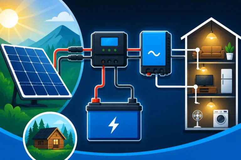
Your inverter and charge controller are the brains and brawn of your off-grid system, and they play a pivotal role in the overall grounding scheme. Virtually all modern inverters and charge controllers, especially reputable brands, come with dedicated grounding lugs or terminals. These are specifically designed points on the device's chassis where you connect your system's equipment grounding conductor.
It’s absolutely vital to follow the manufacturer's instructions for grounding these components. Some manufacturers might require specific grounding configurations, especially for larger, more complex inverter-charger units. For example, a high-quality inverter from a brand like Sol-Ark or Victron will have very clear diagrams for how to connect its chassis to your main grounding electrode conductor (GEC) or to the system's ground bus. Skipping this step, or performing it incorrectly, essentially leaves one of the most critical and potentially dangerous parts of your system vulnerable, rendering much of your other grounding efforts useless. Remember, all metallic enclosures of these devices must be robustly connected to the system's ground to ensure safety during a fault. This level of detail is important when you're looking at Off-Grid Solar System Components Explained.
Step-by-Step Guide to Implementing Off-Grid Grounding and Bonding
Getting your hands dirty with the actual installation of grounding and bonding components might seem daunting, but breaking it down into manageable steps makes it much clearer. This isn't just about throwing some wires together; it's about a methodical approach to electrical safety.
Planning Your Grounding Strategy
Before you even think about driving a ground rod, proper planning is your best friend. Start by performing a thorough load analysis to understand your energy needs and the components you'll be using. With this, you can start identifying all the metallic parts of your system that will need to be bonded. This includes solar panel frames, mounting racks, combiner boxes, inverter and charge controller enclosures, battery racks, and any metal conduit or junction boxes. Don't forget metal structures nearby if they could become energized!
Next, you'll want to assess your soil resistivity. This isn't always easy without specialized equipment, but generally, moist, loamy soil conducts electricity better than dry, sandy, or rocky soil. Knowing your soil type can help you decide if you need one ground rod, two, or even more, and how deep they'll need to go to achieve effective grounding. Finally, and this is crucial, consult your local electrical codes. The National Electrical Code (NEC) provides the baseline, but many states and local municipalities have their own amendments. These codes will dictate everything from the size of your grounding electrode conductor to the depth and spacing of your ground rods. Ignoring these codes not only puts you at risk but can also lead to issues if you ever need an inspection, as discussed in Off-Grid Solar Permit Requirements.
Installing Grounding Electrodes and Main Connections
This is where your plan starts to take physical form.
- Drive the Ground Rods: Using a sledgehammer or a rotary hammer with a specialized ground rod driver bit, drive your 8-foot copper-clad ground rods fully into the earth. Aim for them to be as vertical as possible. If you need multiple rods, ensure they are spaced at least 6 feet apart. The top of the rod should be slightly below grade or easily accessible in a protective box.
- Connect the Grounding Electrode Conductor (GEC): Once the rods are in, you'll connect your GEC to them. Use proper, UL-listed ground rod clamps (often called acorn clamps) that are rated for direct burial. Clean the surface of the ground rod where the clamp will make contact to ensure a solid electrical connection. Tighten these clamps securely.
- Route the GEC to Your Main Equipment: From the ground rod(s), run your GEC (e.g., #6 AWG bare copper wire) to the main grounding bus bar in your primary electrical panel or directly to the main grounding lug on your inverter-charger unit. This path should be as direct as possible and protected from physical damage. You might need to run it through conduit if it's exposed.
Bonding All Components and Running Equipment Grounds
With your main ground established, it’s time to ensure everything else is safely connected.
- Bond Solar Panel Frames and Racking: Each solar panel frame should be bonded to its mounting rail. Many panels have designated grounding points, often marked with a grounding symbol. Use appropriate grounding clips or lugs designed for solar panels, which you can often find from suppliers like Amazon or from specific mounting system manufacturers. The mounting rails themselves then need to be bonded to each other and to a main equipment grounding conductor that leads back to your system's main ground bus. This creates a continuous grounding path from the panels to earth.
- Bond Inverter, Charge Controller, and Battery Enclosures: Locate the grounding lugs on your inverter, charge controller, and any metal battery enclosures. Connect these with properly sized equipment grounding conductors (EGCs) back to the main ground bus in your DC or AC distribution panel. These connections should be clean, tight, and use appropriate crimped lugs where necessary. For detailed guidance on connecting all your major components, refer to resources like How to Wire an Off-Grid Solar System.
- Run Equipment Grounding Conductors (EGCs) Throughout: For every AC and DC circuit leaving your main distribution panel, ensure there’s an EGC running alongside the hot and neutral (or positive and negative) wires. This EGC connects to the metal housings of all your appliances, outlets, and lights, bringing that safety path back to the ground bus. For example, if you're powering a well pump, the EGC will connect to the metal casing of the pump itself.
- Secure and Inspect All Connections: Every single grounding and bonding connection point must be mechanically secure and electrically sound. Use anti-oxidant grease on aluminum connections to prevent corrosion and ensure long-term conductivity. Once everything is connected, do a thorough visual inspection, ensuring no loose wires, frayed insulation, or signs of improper connection. Consider that proper safety also involves components like How to Install Fuses and Breakers to protect circuits.
Here's a handy table outlining the key components for grounding and bonding:
| Component | Purpose in Grounding/Bonding | Key Specification |
|---|---|---|
| Ground Rods | Primary connection to earth for fault current dissipation. | Typically 8 ft length, 5/8" or 3/4" diameter copper-clad steel. |
| Grounding Electrode Conductor (GEC) | Connects main system (inverter/panel) to ground rods. | Sized based on system amperage (e.g., #6 AWG for most residential off-grid). |
| Bonding Jumpers | Connects metal components (panel frames, racks) to create equipotential plane. | Sized based on circuit capacity or manufacturer's spec, often #8 or #10 AWG. |
| Equipment Grounding Conductor (EGC) | Connects appliance/device metal cases to system ground bus. | Runs with circuit conductors, typically same size as circuit wires or smaller per code. |
| Main Ground Bus Bar | Central point within the main panel where all grounding conductors terminate. | Insulated for equipment grounds, bonded for main ground connection. |
| Ground Rod Clamps | Securely connects GEC to ground rod. | UL-listed, direct burial rated (e.g., acorn clamps). |
| Grounding Lugs/Clips | Connects bonding jumpers to solar panel frames and racking. | Specific to panel and racking type, often UL-listed. |
Common Grounding and Bonding Mistakes and Best Practices
Even with the best intentions, it's easy to make mistakes when dealing with something as critical and nuanced as electrical grounding and bonding. Understanding these common pitfalls and adopting best practices can save you headaches, expenses, and potential hazards down the road.
Pitfalls to Avoid in Your Off-Grid Setup
Many DIY off-gridders, in their enthusiasm, might inadvertently overlook details that compromise safety. One of the most common mistakes is inadequate ground rod installation. Driving a rod only a few feet deep, or using too few rods for your soil type, simply won't provide an effective path to earth. Another frequent error is loose or corroded connections. Over time, vibrations, weather, and poor initial tightening can cause connections to loosen, increasing resistance and making your grounding ineffective right when you need it most. Imagine connecting your GEC with a cheap, non-UL-listed clamp from a general hardware store instead of a robust, direct-burial rated one – it might work for a while, but it's a ticking time bomb for corrosion and failure.
Under-sizing grounding conductors is another serious mistake. Using too thin a wire for your GEC or EGCs means it might not be able to carry the full fault current safely, potentially melting or breaking when a surge occurs. Furthermore, forgetting to bond all exposed metallic parts leaves gaps in your safety net. If a metal battery box is left unbonded, it could become energized during a fault without tripping a breaker, becoming a dangerous shock hazard. Relying solely on metallic conduit for grounding is also a no-go; while it provides some path, it’s not always reliable as the primary EGC due to potential loose connections or dissimilar metal corrosion over time. Always ensure a dedicated EGC runs inside the conduit. Ignoring manufacturer-specific grounding instructions for your inverter or charge controller can also void warranties and compromise safety. These are all examples of Common Off-Grid Wiring Mistakes that can be easily avoided with care.
Ensuring Long-Term System Integrity and Safety
Once your system is installed, your commitment to safety isn't over. Regular inspection of all grounding and bonding connections is paramount. Make it a routine, perhaps twice a year, to check for any signs of corrosion, especially on outdoor connections or those exposed to moisture. Look for loose bolts or clamps and tighten anything that feels less than secure. While advanced testing often requires specialized equipment, a visual inspection can catch many potential issues before they become serious.
Consider investing in surge protection devices (SPDs) for both the DC and AC sides of your system. These devices work by diverting lightning strikes and electrical surges safely to ground, but they are only as effective as the grounding system they’re connected to. A robust grounding system ensures these SPDs can do their job effectively, protecting your sensitive and expensive electronics. Remember that maintaining Off-Grid Solar Safety and Grounding is an ongoing process. If you’re ever in doubt about the integrity of your grounding or bonding, especially for a large homestead system, don't hesitate to consult a licensed electrician or an experienced off-grid solar installer. The cost of professional advice pales in comparison to the potential cost of equipment damage or, worse, injury from an electrical accident. For those contemplating the financial aspects of professional help, you might find valuable insights in articles discussing DIY vs Professional Off-Grid Solar Cost and How to Budget for an Off-Grid Solar System.
Disclaimer
The information provided in this guide is for educational and informational purposes only and does not constitute professional electrical advice. Working with electricity, especially in off-grid solar systems, carries inherent risks. Always consult with a qualified, licensed electrician or certified solar installer to ensure your system design and installation comply with all local, state, and national electrical codes and safety standards. Improper installation can result in serious injury, death, or property damage.