How to Size Wire and Cables
Oh, the sheer headache of staring at a bundle of wires, trying to figure out if that seemingly beefy cable is actually enough for your precious off-grid setup! It’s a common pitfall for so many of us embarking on the solar journey, leading to everything from frustrating power losses to, frankly, dangerous situations. This guide is here to untangle that confusion, walking you through the critical process of properly sizing wires and cables for your off-grid solar system to ensure it runs safely, efficiently, and reliably for years to come.
Why Proper Wire Sizing is Absolutely Critical for Off-Grid Solar
When you're building an off-grid solar system, it's easy to get caught up in the big components like panels, batteries, and inverters. But those humble wires and cables? They are the literal veins of your system, carrying all that hard-won energy. Skimping on their size or making assumptions can lead to a cascade of problems that undermine your entire investment and even pose a risk.
Preventing Voltage Drop and Power Loss
Imagine trying to drink water through a ridiculously thin straw. It takes a lot more effort, and you get very little water. That's essentially what happens with undersized wires: they act like a bottleneck, resisting the flow of electricity. This resistance causes something called "voltage drop." Every foot of undersized wire contributes to this drop, meaning less voltage and less power actually make it to your appliances or, critically, your battery bank.
This isn't just a minor inconvenience; it significantly impacts your system's performance. Your refrigerator might not run as cold, your lights could flicker, or your well pump might struggle, potentially shortening its lifespan. Even worse, if your charge controller is sending power to your batteries through too-small wires, those batteries won't get a full charge, leaving you with less usable power and reducing the overall health and longevity of your expensive battery bank. Every watt lost to voltage drop is a watt you worked hard to generate but never got to use. It's like having money literally evaporate from your wallet before you even spend it.
Ensuring Safety and Preventing Fires
Beyond inefficiency, using wires that are too small for the current they carry is a serious safety hazard. When electricity flows through a resistive wire, it generates heat. The more current and the smaller the wire, the more heat is produced. If a wire can't dissipate that heat effectively, its insulation can melt, leading to short circuits. In severe cases, this overheating can ignite nearby flammable materials, turning your dream off-grid cabin or RV into a nightmare.
While circuit breakers and fuses are essential for protecting your equipment from overcurrents, they primarily protect against fault conditions like a short circuit or an appliance drawing too much power. They don't always protect against prolonged overheating due to chronically undersized wiring under normal, continuous load conditions. The wire itself might be slowly cooking before the breaker ever trips. Imagine connecting a powerful electric kettle in your tiny home with a wire meant for a small lamp – the wire would get dangerously hot, quickly becoming a fire risk. This is why proper wire sizing is the first line of defense against electrical fires in your off-grid sanctuary. For a deeper dive into overall system safety, check out our Off-Grid Solar Installation Guide.
Key Factors Influencing Wire Size Selection
Choosing the right wire size isn't a shot in the dark; it's a careful calculation based on several crucial factors. Think of it like designing a plumbing system – you need to consider water pressure, flow rate, and pipe length to ensure water gets where it needs to go without bursting pipes or trickling out.
System Voltage and Current Amperage
This is arguably the most critical factor. The fundamental relationship between power, voltage, and current (P = V * I, where P is power in watts, V is voltage in volts, and I is current in amperes) dictates a simple but profound truth: for the same amount of power, a higher voltage means a lower current. And lower current means you can often use thinner wires.
Consider a 1000-watt load. If you're running it on a 12-volt system (common in RVs or smaller setups), that's roughly 83 amps (1000W / 12V = 83.3A). If you're running the same 1000-watt load on a 48-volt system (typical for larger homes or cabins), that's only about 21 amps (1000W / 48V = 20.8A). That difference – 83 amps versus 21 amps – is massive when it comes to wire sizing. The 12-volt system will require significantly thicker, more expensive cables to handle the higher current safely and efficiently, especially between your battery bank and inverter. This is why many larger off-grid systems opt for higher voltages like 48V; it makes wiring more manageable and cost-effective. You can learn more about this decision in 12V vs 24V vs 48V: Which to Choose.
Distance of the Wire Run
Electricity isn't magic; it encounters resistance as it travels through a conductor. The longer the wire, the more resistance it encounters, and consequently, the greater the voltage drop. It’s a bit like a long-distance runner getting tired over time – the further they go, the more energy they expend. For electrical circuits, this "energy expended" manifests as heat and voltage loss.
When calculating the distance, remember that it's a two-way trip: from the power source (like your solar panels or battery) to the load (your appliance or inverter) and back. So, if your solar panels are 25 feet from your charge controller, your effective wire run for calculation purposes is 50 feet. It's crucial to minimize these distances, especially for high-current DC circuits. Longer distances necessitate larger wire gauges to keep voltage drop within acceptable limits. Trying to power a shed 100 feet from your battery bank with thin wires will result in pitiful performance, if any.
Conductor Material and Temperature
While copper is king for most off-grid solar wiring due to its excellent conductivity and resistance to corrosion, it's not the only material. Aluminum is sometimes used for very large service entrance cables, but it's generally avoided for smaller, finer wiring in off-grid systems because it's less conductive than copper and can be more challenging to terminate reliably without specialized connectors to prevent oxidation. For the typical DIYer or even professional off-grid installer, copper is the go-to.
Temperature also plays a significant role. Wires carrying current generate heat, and their ability to carry current safely is rated for specific ambient temperatures. If a wire is installed in a hot environment (like a sealed conduit in a hot attic, or a buried cable in a desert climate, or simply operating in high summer temperatures), its current-carrying capacity (ampacity) is effectively reduced. This is called "temperature derating." The National Electrical Code (NEC) provides specific tables for adjusting ampacity based on ambient temperature. Failing to account for this can lead to overheating, even if your calculations seemed correct for a moderate climate. Always err on the side of caution in hot environments; a wire that's perfectly fine in Minnesota winter might struggle in Arizona summer.
Conductor Insulation and Installation Method
The outer jacket, or insulation, of your cable isn't just for protection; it also impacts how the wire dissipates heat and therefore its allowable ampacity. Different types of insulation are rated for different environments:
- THHN/THWN: Common building wire, usually for dry or wet (THWN) indoor use in conduit.
- USE-2/RHW-2: Designed for outdoor underground or exposed solar applications, highly UV resistant and wet rated. These are often what you’ll find as the dedicated solar panel wiring.
- UF-B: Underground Feeder cable, suitable for direct burial, commonly used for branch circuits.
The way your wires are installed directly affects their heat dissipation. Wires bundled together in conduit, or running through insulation in a wall, can't shed heat as easily as a single, exposed wire. The NEC provides "ampacity adjustment factors" for wires grouped in conduits or cables to account for this reduced cooling. For instance, if you have more than three current-carrying conductors in a single conduit, you typically have to "derate" their ampacity. Ignoring these factors can lead to localized overheating, even if the general wire gauge appears sufficient. This is part of the broader Off-Grid Solar Wiring Best Practices you should always consider.
The Step-by-Step Process for Sizing Your Off-Grid Cables
Now that we understand the 'why' and the 'what,' let's get down to the 'how.' Sizing your off-grid cables isn't rocket science, but it does require a methodical approach. Skipping steps here is a recipe for trouble. This process is a crucial part of How to Size an Off-Grid Solar System overall.
Calculating Your Maximum Amperage
This is the cornerstone of wire sizing. You absolutely must know the maximum current (amperage) that will flow through each segment of your wiring. Remember, P = V * I. So, if you know the power (watts) of an appliance or the maximum output of your solar array, and you know the voltage, you can calculate the current.
- For DC Circuits (Solar Panels, Charge Controller, Batteries):
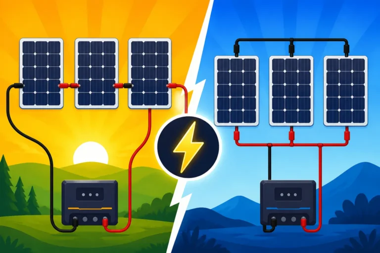
- Solar Panels to Charge Controller (PV array circuit): You'll need to consider the maximum short-circuit current (Isc) of your solar panels. If you have multiple panels, sum the Isc for parallel strings or use the Isc of a single panel for series strings. The NEC recommends multiplying this value by 1.25 for continuous operation, plus another 1.25 for possible overcurrent, giving you a factor of 1.56. So,
Max_PV_Current = (Panel_Isc * Number_of_Parallel_Strings) * 1.56. - Charge Controller to Battery Bank: This is often a high-current path. Use the maximum output current rating of your charge controller. Again, multiply by 1.25 for continuous load.
- Battery Bank to Inverter: This is typically the highest current path in your system. Calculate the maximum continuous AC output power of your inverter, divide by your battery bank voltage, and then multiply by an efficiency factor (usually 1.15 to 1.25) to account for inverter losses, plus the 1.25 continuous load factor. So,
Max_Inverter_DC_Current = (Inverter_Max_AC_Power / Battery_Voltage) * 1.25 (for inverter efficiency) * 1.25 (for continuous load).
- Solar Panels to Charge Controller (PV array circuit): You'll need to consider the maximum short-circuit current (Isc) of your solar panels. If you have multiple panels, sum the Isc for parallel strings or use the Isc of a single panel for series strings. The NEC recommends multiplying this value by 1.25 for continuous operation, plus another 1.25 for possible overcurrent, giving you a factor of 1.56. So,
- For AC Circuits (Inverter to AC Loads, Generator to Inverter Charger):
- Calculate the maximum current draw of your AC loads. For example, a 1500W microwave on a 120V AC circuit is 12.5A (1500W / 120V = 12.5A). Again, apply the 1.25 continuous load factor for circuits that might run for extended periods.
Keep in mind that you need to do a thorough Off-Grid Solar Load Calculation Explained to ensure you're accounting for all your devices.
Determining Voltage Drop Tolerance
Once you have your maximum current, the next step is to decide how much voltage drop you're willing to accept. This is a balancing act between efficiency and cost, as larger wires (to reduce voltage drop) are more expensive. General recommendations are:
- Solar PV Circuits (Panels to Charge Controller): Aim for no more than 2-3% voltage drop. Losing power here means less energy making it into your batteries.
- Charge Controller to Battery Bank: This is a crucial, high-current path. Keep voltage drop here to 1-2% for optimal charging efficiency and battery health.
- Battery Bank to Inverter: Another critical high-current path. Aim for 2-3% voltage drop to prevent the inverter from shutting down prematurely under heavy loads due to perceived low voltage.
- AC Circuits (Inverter to Loads): Standard electrical practice typically allows for up to 3% voltage drop for branch circuits and up to 5% for feeder and branch circuit combined.
If you calculate a voltage drop higher than your target, you'll need to increase your wire size. There are plenty of online calculators and charts that can help you with this, and some solar-specific brands like Renogy offer their own guidance, often included in their product manuals or on their websites.
Using Wire Sizing Charts and Calculators
After determining your maximum current and acceptable voltage drop, you can use specialized charts or online calculators to find the appropriate wire gauge. These tools take into account:
- Current (Amps): The maximum current you calculated.
- Voltage (Volts): Your system's operating voltage (e.g., 12V, 48V, 120V AC).
- Distance (Feet/Meters): The one-way distance, which the calculator often doubles for the round trip.
- Voltage Drop Percentage: Your desired tolerance.
- Conductor Material: Usually copper.
Many electrical supply houses and solar equipment manufacturers, as well as general resources found on Amazon or other marketplaces, provide these charts. They usually list American Wire Gauge (AWG) sizes, with smaller AWG numbers indicating thicker wires (e.g., 10 AWG is thicker than 14 AWG, and 2/0 AWG is much thicker than 1 AWG).
Example Scenario:
Let's say you have a 12V system and want to run a 20A circuit to a refrigerator that's 20 feet away. You want a maximum of 3% voltage drop.
Using an online calculator (like one from Blue Sea Systems or similar electrical resources), you would input:
- Voltage: 12V
- Amps: 20A
- Distance: 20 feet (calculator typically accounts for round trip)
- Desired Voltage Drop: 3%
The calculator would likely recommend a 6 AWG or 8 AWG wire, depending on the exact calculator and specific voltage drop target. If you had chosen a 10% voltage drop (which is generally too high for critical off-grid loads), it might suggest a smaller, cheaper wire, but at the expense of performance. Always prioritize the efficiency and safety aspect.
It's wise to double-check your calculations with at least two different tools or charts to ensure accuracy. For general guidance on circuit wiring, you might find more details in our comprehensive How to Wire an Off-Grid Solar System guide.
Specific Wire Sizing for Each Off-Grid Component
Each segment of your off-grid solar system has unique demands, and therefore, unique wire sizing considerations. It's not a one-size-fits-all approach.
Solar Panel to Charge Controller Wiring
The wiring from your solar panels to your charge controller is your PV array circuit. While the current might not be as high as the battery-to-inverter path, especially in higher voltage series-wired arrays, voltage drop is still critical here. Every bit of voltage lost between your panels and your charge controller means less power available for charging your batteries.
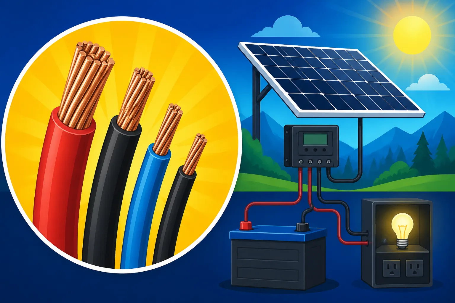
You'll need specialized PV wire, which is typically single-conductor, direct burial rated, and UV resistant (like USE-2 or PV Wire rated). The wire size here is determined by the total short-circuit current (Isc) of your parallel strings (if you're wiring panels in parallel) or the Isc of a single panel (if you're wiring panels in series), plus the 1.56 safety factor mentioned earlier. For example, if you have four 100W panels, each with an Isc of 6A, wired in two parallel strings of two series panels, your max current would be 12A * 1.56 = ~18.7A. If the run is 30 feet, you'll need to consult a wire sizing chart for 18.7A at your system voltage (e.g., 24V or 48V) to achieve a 2-3% voltage drop. Often, for smaller systems, 10 AWG or 8 AWG PV wire is common, but larger systems will need thicker gauges. Don't forget to properly protect these circuits with appropriate fuses or breakers, usually in a combiner box. Learning How to Wire Solar Panels in Series can influence your current and thus your wire size requirements.
Charge Controller to Battery Bank Wiring
This connection is arguably one of the most critical and often underestimated in terms of current. Whether you're using an MPPT or PWM charge controller, it's channeling all the power harvested from your solar panels directly into your battery bank. If this path has too much resistance (i.e., undersized wires), you're literally choking the flow of energy to your batteries.
The current here is the maximum output current of your charge controller, multiplied by 1.25 for continuous operation. Because battery banks are typically lower voltage (12V, 24V, or 48V), and the current can be quite high, these cables need to be substantially thicker than your PV array wiring. For instance, a 60A charge controller on a 12V system could output up to 75A (60A * 1.25). For even a short, 5-foot run, you might need 4 AWG or even 2 AWG cable to keep the voltage drop under 2%. For 24V or 48V systems, the current will be lower for the same wattage, allowing for smaller gauges, but still significant. Always use stranded copper wire for flexibility and durability, and ensure terminations are robust. Don't forget a correctly sized fuse or breaker within 7 inches of the battery positive terminal for safety, as detailed in How to Connect a Charge Controller.
Battery Bank to Inverter Wiring
This is almost always the highest current-carrying section of your entire off-grid system, especially if you have a powerful inverter designed to run AC appliances. When your inverter is pulling heavy loads – like a microwave, a well pump, or an air conditioner – it can draw hundreds of amps from your battery bank in a 12V or 24V system.
For example, a 3000-watt inverter on a 12V system could draw over 250 amps (3000W / 12V = 250A) continuously, even before accounting for startup surges or inverter efficiency losses. With the 1.25 continuous factor, you're looking at over 300 amps. For such high currents, you're talking about extremely thick cables, often 2/0 AWG, 4/0 AWG, or even larger, and they must be kept as short as physically possible – ideally less than 3-5 feet. Long, thin cables here will cause a massive voltage drop, making your inverter inefficient or even causing it to shut down under load, giving you frustrating "low voltage" errors. This is where quality, robust battery cables from reputable suppliers or brands like Renogy really shine. Always install a correctly sized DC-rated fuse or circuit breaker close to the battery bank, ahead of the inverter. For guidance on sizing this component, see How to Size an Off-Grid Inverter. This critical connection also highlights the importance of precise battery wiring as described in How to Connect an Inverter to Batteries.
AC Wiring for Inverter Output
Once your inverter converts the DC power from your batteries into usable AC power, the wiring then largely follows standard household electrical codes (like the National Electrical Code in the US). This means you'll use standard AC-rated copper wire, typically multi-strand for flexibility, like THHN or Romex-style (NM-B) cable for indoor applications.
The sizing here is determined by the maximum amperage of your AC circuits and the voltage (typically 120V or 240V). Common residential wire sizes include:
- 14 AWG: For 15-amp circuits (e.g., lighting, small electronics).
- 12 AWG: For 20-amp circuits (e.g., kitchen receptacles, heavier-duty power tools).
- 10 AWG: For 30-amp circuits (e.g., some larger appliances, small electric water heaters).
- 8 AWG or larger: For high-draw 240V appliances like electric ranges or larger water heaters.
Always follow local electrical codes for AC wiring, including proper grounding, conduit usage where required, and appropriate circuit breaker protection in an AC distribution panel. The voltage drop calculations for AC circuits are similar but generally less critical than high-current DC runs, thanks to the higher operating voltage.
Practical Tips and Common Mistakes
Venturing into off-grid solar can be incredibly rewarding, but it’s full of little details that can trip you up. Wire sizing is one of those areas where a small oversight can have big consequences.
Always Round Up and Plan for the Future
If your calculations suggest a wire size that's on the borderline between two gauges, always round up to the next thicker size. For instance, if your calculation lands you needing something equivalent to an 8.5 AWG, go with a 6 AWG. It's a small additional cost upfront, but the benefits of reduced voltage drop, increased efficiency, and a significant boost in safety are immeasurable. Trying to save a few dollars by choosing an undersized wire is a false economy; the reduced performance, potential safety hazards, and eventual need to replace the wiring will cost you far more in the long run.
Moreover, if there's any chance you might expand your system in the future – adding more solar panels, a larger inverter, or more appliances – consider sizing your main feeder cables a bit larger than your immediate needs. It’s far easier and cheaper to install slightly oversized cables once than to tear apart your system to upgrade them down the line. Planning for future expansion is a smart move that often gets overlooked, but it can save you a world of headache and expense. You can get more insights on preparing for future needs in How to Plan for Future Expansion.
Importance of Fuses, Breakers, and Proper Terminations
Wire sizing isn't just about the conductor itself; it's part of a complete safety system that includes overcurrent protection. Fuses and circuit breakers are there to protect your wires and equipment from excessive current that could damage them or cause a fire. Your fuses and breakers should always be sized to protect the smallest component in the circuit, which is often the wire itself. For example, a 10 AWG wire might be rated for 30 amps, so a 30A fuse or breaker would be appropriate. You wouldn't put a 50A breaker on a 10 AWG wire, as the wire could overheat and melt before the breaker trips.
Beyond sizing, proper termination is paramount. A wire could be perfectly sized, but if it's connected poorly – with loose screws, improperly crimped lugs, or corroded terminals – it creates localized resistance, heat, and potential failure points. Always use high-quality crimping tools for lugs, ensure all connections are tight and secure, and consider using heat-shrink tubing to protect exposed connections from moisture and corrosion. Many premium off-grid components from brands like Victron or Outback include detailed instructions on proper cable termination, emphasizing the critical nature of these connections.
Understanding AWG and Metric Wire Gauges
When you're shopping for wire, you'll encounter different systems for designating wire size. The most common in North America is AWG (American Wire Gauge). With AWG, smaller numbers mean thicker wires. So, 10 AWG is thicker than 14 AWG, and 2/0 AWG (pronounced "two aught") is much thicker than 1 AWG. It can be a bit counter-intuitive at first, but you'll get used to it.
In other parts of the world, and sometimes on imported components, you might see wire sizes specified in square millimeters (mm²). With metric sizing, larger numbers mean thicker wires. So, a 6 mm² wire is thicker than a 4 mm² wire.
Here's a quick reference table for common DC wire gauges and their approximate cross-sectional area, along with typical ampacities (current-carrying capacity) in an ideal scenario (always verify with specific charts and derating factors):
| AWG Gauge (Approx.) | Metric Area (mm²) (Approx.) | Typical Max Amps (12V, Short Run) | Common Off-Grid Application |
|---|---|---|---|
| 14 AWG | 2.08 mm² | 15-20A | Small DC lights, charging low-power devices |
| 12 AWG | 3.31 mm² | 20-25A | Medium DC loads, panel strings for small systems |
| 10 AWG | 5.26 mm² | 30-40A | PV array wiring, small charge controller output |
| 8 AWG | 8.37 mm² | 50-60A | PV array wiring for larger systems, main DC runs |
| 6 AWG | 13.3 mm² | 75-80A | Main DC runs, charge controller to battery |
| 4 AWG | 21.1 mm² | 100-120A | Main DC runs, inverter connections (smaller inverters) |
| 2 AWG | 33.6 mm² | 150-175A | Inverter connections, main battery bank cables |
| 1/0 AWG (0 AWG) | 53.5 mm² | 200-225A | Larger inverter connections, main battery bank cables |
| 2/0 AWG (00 AWG) | 67.4 mm² | 250-300A | High-power inverter connections (e.g., 2000W+ on 12V) |
| 4/0 AWG (0000 AWG) | 107.2 mm² | 350-400A | Very high-power inverter connections (e.g., 3000W+ on 12V) |
Note: These ampacities are for general reference in short runs and ideal conditions. Always use a proper wire sizing calculator and account for voltage drop, temperature, and installation method.
When purchasing wire, especially online from platforms like Amazon or directly from suppliers, always confirm the AWG or mm² rating, the conductor material (stranded copper is best), and the insulation type to ensure it meets your specific off-grid solar requirements. Getting this right is fundamental to the long-term success and safety of your system.
Disclaimer
The information provided in this guide is for general educational and informational purposes only and does not constitute professional electrical advice. Off-grid solar system design and installation can be complex and potentially dangerous. Always consult with a qualified electrician or solar professional and adhere to all local and national electrical codes (such as the NEC) when designing or installing your system. Improper installation can result in property damage, serious injury, or death.