How to Wire an Off-Grid Solar System
Feeling overwhelmed by the spaghetti of wires and diagrams when thinking about off-grid solar? You're not alone! The prospect of electrifying your remote cabin, RV, or homestead can be exhilarating, but the actual wiring process often feels like tackling a complex puzzle with high stakes. This comprehensive guide is designed to demystify the art of wiring an off-grid solar system, breaking down each step into manageable, understandable pieces, ensuring your journey to energy independence is safe, efficient, and successful.
Understanding the Fundamental Components of an Off-Grid System
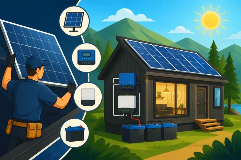
Before we even touch a wire, it's crucial to understand the main players in any off-grid solar system. Think of it like assembling a team – each member has a specific role, and they all need to work together seamlessly for the mission to succeed. Knowing what each component does will make the wiring process much clearer and help you troubleshoot if issues arise down the road.
The Solar Panels: Your Energy Harvesters
Solar panels are the workhorses of your system, quietly converting sunlight into usable electricity. These clever devices contain photovoltaic (PV) cells that absorb photons from the sun and release electrons, creating a direct current (DC) flow. The amount of power they produce depends on their wattage, the intensity of the sun, and how efficiently they capture light.
There are various types of solar panels, with monocrystalline and polycrystalline being the most common for off-grid applications. Monocrystalline panels, often characterized by their uniform dark color, tend to be more efficient and perform better in lower light conditions, making them a popular choice despite a slightly higher cost. Polycrystalline panels are a bit less efficient but more budget-friendly. Regardless of type, your panels will come with positive (+) and negative (-) terminals, typically in the form of MC4 connectors, which are essential for creating a secure, weatherproof connection to the rest of your system. You can often find a great selection of these on platforms like Amazon or from specialized solar retailers.
The Charge Controller: The Battery's Gatekeeper
Once your solar panels convert sunlight into DC electricity, that power needs to be managed before it can be stored in your batteries. This is where the charge controller steps in. Its primary job is to regulate the voltage and current coming from your solar array, ensuring your batteries are charged efficiently without being overcharged or damaged. Overcharging is a serious risk that can shorten battery life or even lead to dangerous failures, especially with certain battery chemistries.
There are two main types of charge controllers you'll encounter: Pulse Width Modulation (PWM) and Maximum Power Point Tracking (MPPT). PWM controllers are simpler and more affordable, best suited for smaller systems where the solar panel voltage closely matches the battery bank voltage. MPPT controllers, while more expensive, are significantly more efficient, especially in larger systems or when there's a significant voltage difference between the panels and batteries. An MPPT controller can "track" the optimal voltage and current point of your solar array to extract the maximum available power, often increasing energy harvest by 10-30%. Understanding How to Choose an Off-Grid Charge Controller is vital to protecting your battery investment.
The Battery Bank: Your Power Reservoir
If solar panels are the engine, the battery bank is your fuel tank. Off-grid living means you don't have the utility grid to fall back on when the sun isn't shining. Your batteries store the excess energy generated by your solar panels during the day, making it available for use at night or on cloudy days. Without a robust battery bank, your off-grid system simply wouldn't be able to provide continuous power.
The choice of battery chemistry is a huge decision that impacts cost, lifespan, and performance. Lead-acid batteries (like flooded, AGM, or Gel) are traditional, more budget-friendly upfront, but require more maintenance and have shorter lifespans. Lithium-iron phosphate (LiFePO4) batteries are becoming increasingly popular for off-grid systems due to their much longer cycle life, deeper discharge capabilities, lighter weight, and zero maintenance. While their initial cost is higher, their longevity and performance often make them more cost-effective over the long term. Properly sizing and maintaining your battery bank is critical to the reliability and longevity of your entire off-grid setup. You’ll need to figure out How Many Batteries for an Off-Grid System based on your energy demands.
The Inverter: From DC to AC Power
Most modern appliances and electronics run on alternating current (AC) power, the same kind of electricity you get from the wall outlets in a grid-tied home. However, your solar panels and batteries produce and store direct current (DC) power. This is where the inverter comes into play. It's the magical box that converts the DC power from your battery bank into usable AC power for your home, cabin, or RV.
Just like with charge controllers, there are different types of inverters. Pure sine wave inverters produce a clean, consistent waveform, identical to grid power, which is essential for sensitive electronics like laptops, medical equipment (like CPAP machines), and appliances with motors. Modified sine wave inverters are less expensive but produce a "choppier" waveform, which can cause issues with some electronics, leading to buzzing, overheating, or even damage. For any serious off-grid application, a pure sine wave inverter is almost always the recommended choice. Inverter size, measured in watts, must match your peak power demands, meaning the total wattage of all appliances you might run simultaneously. You might also encounter inverter-chargers, like some offerings from Victron or Sol-Ark, which combine the functions of an inverter and a battery charger into one unit, often with generator integration capabilities.
Essential Tools and Safety Precautions for Wiring
Diving into wiring without the right tools and a solid understanding of safety protocols is like trying to build a house with a spoon – it's going to be inefficient, dangerous, and likely lead to disaster. Electrical work, even low-voltage DC, carries inherent risks. A little preparation goes a long way in preventing accidents and ensuring your system is wired correctly from the start.
Tools of the Trade for Off-Grid Wiring
Having the right tools isn't just about convenience; it's about making precise, secure connections that are vital for the long-term reliability and safety of your solar system. You wouldn't want loose wiring leading to voltage drops, inefficiencies, or worse, a fire hazard.
Here's a list of essential tools you'll need:
- Wire Strippers: Get a good quality pair that can handle various wire gauges, especially larger sizes for battery cables. Clean, precise cuts are crucial to avoid damaging the copper strands.
- Crimpers: For making secure connections with lug terminals. High-quality hydraulic or heavy-duty manual crimpers are a must for battery cables and other large gauge wires. Don't skimp here; a poor crimp is a weak point in your system.
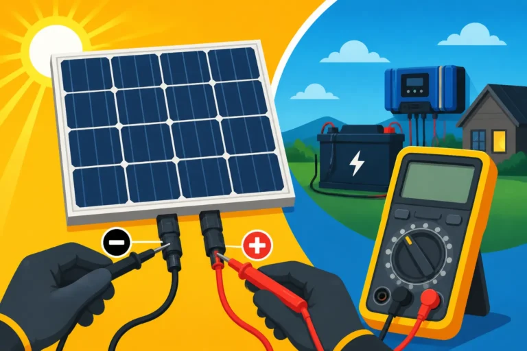
- Multimeter (Voltmeter/Ammeter): Absolutely non-negotiable. You'll need this to test voltages, confirm polarity, and check for continuity at every stage of your wiring process. A clamp meter can also be incredibly useful for measuring current without breaking the circuit.
- Assorted Screwdrivers and Wrenches: For tightening terminals, mounting components, and securing covers.
- Cable Cutters: For cleanly cutting heavy gauge wires without fraying.
- Heat Gun (for heat-shrink tubing): Essential for weatherproofing and insulating exposed connections, especially outdoors or in damp environments.
- Drill: For mounting panels, components, and running conduit.
- Conduit Bender (if using rigid conduit): For professional-looking and protected wire runs.
You can find many of these tools, and even specialized solar wiring toolkits, readily available on Amazon, making it convenient to gather everything you need before you start.
Prioritizing Safety: It's Not Just a Suggestion
Electricity demands respect, and off-grid solar systems, even those operating at lower DC voltages, can deliver significant current that can be dangerous. Never underestimate the potential for serious injury or fire. Always approach wiring with caution and adhere to strict safety practices.
Here are the safety precautions you must follow:
- Disconnect Power FIRST: Before touching any wires or making any connections, always ensure all power sources are disconnected. This means covering your solar panels to prevent them from generating electricity (a blanket or tarp works), disconnecting your battery bank, and ensuring your inverter is off and disconnected from any loads. Treat every wire as if it's live until you've verified otherwise with your multimeter.
- Wear Personal Protective Equipment (PPE): This includes insulated gloves (especially when working with batteries), safety glasses to protect against sparks or acid splashes, and appropriate non-conductive footwear.
- Proper Grounding: Ensure your entire system is properly grounded to earth. This provides a safe path for fault currents in case of a short circuit or lightning strike, protecting both your equipment and anyone near it. We'll delve into How to Ground an Off-Grid Solar System later in this guide.
- Work in a Dry Environment: Never work with electricity in wet conditions. Water is a conductor and significantly increases the risk of electrocution.
- Understand Polarity: DC circuits are all about positive (+) and negative (-). Reversing polarity can severely damage components like charge controllers and inverters. Double-check every connection with your multimeter before energizing the system.
- Ventilation for Batteries: If you're using flooded lead-acid batteries, ensure they are in a well-ventilated area, as they can off-gas hydrogen and oxygen during charging, which is flammable. LiFePO4 batteries are generally safer in this regard but still benefit from good airflow.
Remember, a momentary lapse in safety can have lasting consequences. Take your time, double-check your work, and if you're ever unsure, consult with a qualified electrician or solar professional.
Wiring Your Solar Panels to the Charge Controller
This is where the journey of solar power generation truly begins in your off-grid system. The solar panels gather the energy, and the charge controller is the first piece of equipment that handles it. Getting this connection right is paramount for efficient energy capture and protection.
Configuring Your Solar Array: Series or Parallel
Before you even think about connecting wires, you need to decide how your individual solar panels will be arranged. This choice—series, parallel, or a combination of both (series-parallel)—directly impacts the voltage and current characteristics of your solar array, which in turn affects what kind of charge controller you need and the efficiency of your system.
- Series Wiring: When you wire panels in series, you connect the positive terminal of one panel to the negative terminal of the next. Think of it like a string of Christmas lights. This configuration adds the voltage of each panel while keeping the current (amperage) the same. For example, two 12-volt panels in series will produce 24 volts at the current of a single panel. This is often preferred for longer wire runs, as higher voltage reduces current, which in turn reduces voltage drop over distance and allows for thinner (and less expensive) wiring. It's especially useful when pairing with an MPPT charge controller, which thrives on higher input voltages.
- Parallel Wiring: In parallel wiring, all positive terminals are connected together, and all negative terminals are connected together. This setup adds the current of each panel while keeping the voltage the same. So, two 12-volt panels in parallel will produce 12 volts at double the current of a single panel. Parallel connections are great for smaller systems or when you need to match a lower battery bank voltage, like a 12V RV system. However, higher currents necessitate thicker wiring to prevent voltage drop and overheating.
- Series-Parallel Wiring: For larger systems, you might use a combination. You could wire several panels in series to create a "string" of higher voltage, and then connect multiple such strings in parallel. This allows you to achieve both higher voltage and higher current outputs, optimizing your array for a specific charge controller or system voltage. Understanding How to Wire Solar Panels in Series vs Parallel is a foundational skill for any off-grid enthusiast, as it directly impacts your system's performance and component compatibility.
The key is to match your array's voltage and current output to the input specifications of your charge controller and, ultimately, your battery bank. An MPPT charge controller often works best with a higher voltage input from the panels (e.g., 60-80V) than the battery bank (e.g., 24V or 48V), allowing it to efficiently step down the voltage while stepping up the current to charge the batteries.
Connecting Panels to the Combiner Box
Once your panels are configured in series, parallel, or series-parallel, the wires from your array need to come together. This is typically done at a combiner box, especially for systems with multiple strings of panels. A combiner box serves several critical functions: it consolidates the wiring, provides overcurrent protection for each string, and acts as a central point for a DC disconnect switch.
Each string of panels will have its positive and negative wires running into the combiner box. Inside, these wires will connect to fuses or circuit breakers—one for the positive line and one for the negative line for each string. This protects individual panel strings from damage if a fault occurs in one of them, preventing the entire array from failing and isolating the issue. The outputs of these fuses/breakers then converge into a single, larger positive and negative output cable that runs to your charge controller. Ensure that all connections are tight, and use appropriate wire glands to seal cable entry points into the combiner box, protecting connections from moisture and pests. Many quality combiner boxes can be found from brands like Renogy or through various suppliers on Amazon.
Running Wires from the Combiner Box to the Charge Controller
With your solar array configured and consolidated in the combiner box, the next step is to run the main DC cables from the combiner box to your charge controller. These cables carry the raw power from your panels and are critical for minimizing energy loss.
Here's how to approach it:
- Determine Wire Gauge: This is crucial. The wire gauge you need depends on the total current (amps) your array will produce and the distance between the combiner box and the charge controller. Undersized wires will lead to significant voltage drop, meaning you lose power as heat in the wires, and can even pose a fire risk. Use a wire gauge calculator or consult the National Electrical Code (NEC) tables to ensure you're using appropriately sized wires. For example, a 10-gauge wire might be sufficient for a short run with a small array, but a large system might require 4-gauge or even 2-gauge wire for longer distances.
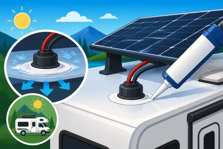
- Route Cables Safely: Run your cables in conduit (rigid or flexible, depending on local codes and environment) to protect them from physical damage, UV degradation, and animals. Route them neatly, avoiding sharp bends and potential pinch points. If going through walls or roofs, ensure all penetrations are sealed effectively to prevent water intrusion.
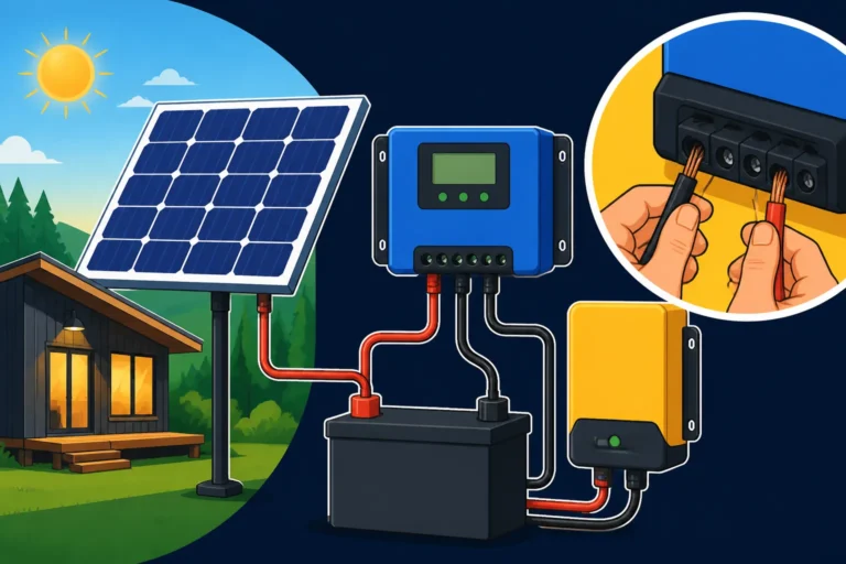
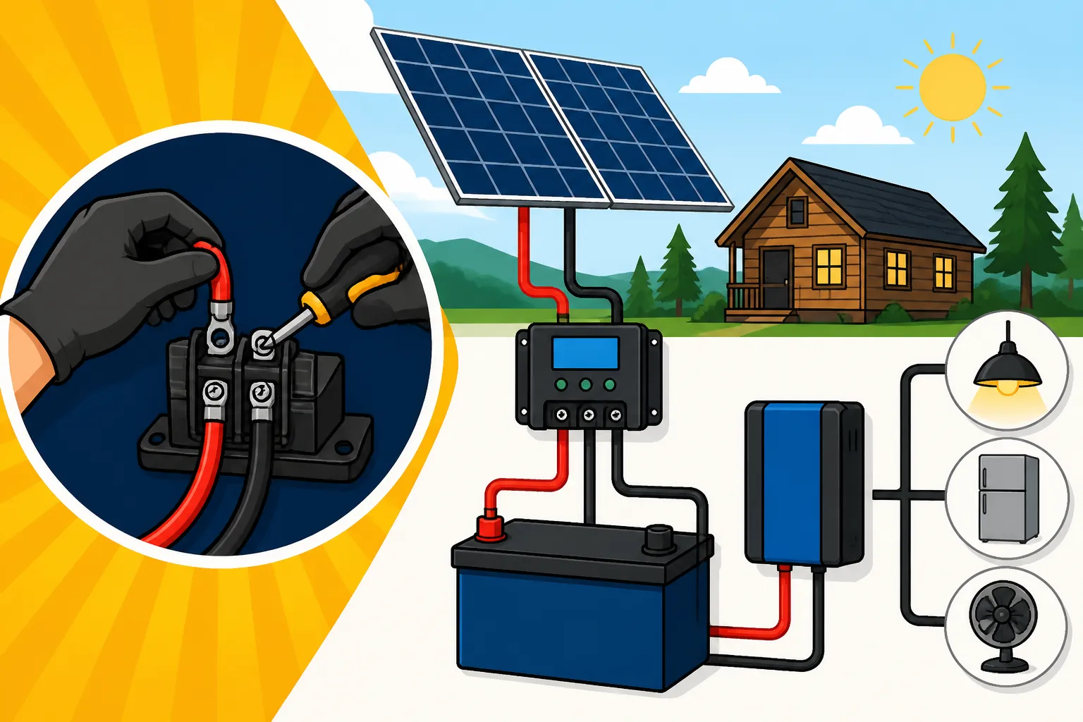
- Connect to Charge Controller: At the charge controller, you'll find clearly marked terminals for "PV Input" or "Solar Array." Double-check polarity: connect the positive (+) wire from the combiner box to the positive PV input terminal on the charge controller, and the negative (-) wire to the negative PV input terminal. Ensure all terminal screws are tightened securely. Do not connect the battery terminals of the charge controller yet. The charge controller needs to see the battery voltage first before it's connected to the solar panels, but for safety during initial wiring, we typically connect battery first (after all wiring is complete and checked) and solar last. For now, ensure only the solar input wires are connected to the charge controller.
This stage effectively sets up the "generation" side of your off-grid system. You've harnessed the sun's power and brought it to the intelligent regulator that will prepare it for storage.
Integrating the Charge Controller with Your Battery Bank
Now that your solar panels are connected to the charge controller, the next step is to connect the charge controller to your battery bank. This is the heart of your off-grid system, as it's where the generated power is stored for later use. Precise wiring and appropriate protection are critical here to ensure both safety and optimal battery life.
Wiring the Charge Controller to the Battery Bank
This connection is arguably one of the most important in your system, as it's where the regulated power meets your precious energy storage. The charge controller will actively monitor your battery bank's state of charge and adjust the charging profile to maximize battery health and longevity.
Here's a detailed breakdown:
- Prioritize Safety First: Before making any connections to your battery bank, ensure your solar panels are covered or disconnected from the charge controller, and your inverter (if already present) is completely off and isolated. Batteries, especially large banks, can deliver massive amounts of current, and a short circuit can be extremely dangerous, causing severe burns, explosions, or fires.
- Determine Wire Gauge: Just like with your solar array wiring, the wire gauge for the charge controller-to-battery connection is crucial. This wire needs to handle the maximum charging current your charge controller will send to the batteries. Use a wire gauge calculator considering the current and the distance. Shorter, thicker wires are always better for this critical connection to minimize voltage drop and ensure efficient charging.
- Install Fuses or Breakers: A critical safety component in this circuit is a fuse or circuit breaker placed as close as possible to the battery bank on the positive (+) line. This protects your wiring and charge controller from overcurrent in case of a fault. The size of this fuse or breaker should be rated slightly above the maximum output current of your charge controller. For instance, if your charge controller has a maximum output of 60 amps, a 70-amp fuse would be a good choice.
- Connect to Battery Terminals:
- Positive Connection: Route the positive (+) wire from the charge controller's "Battery Output" terminal to one side of your inline fuse or circuit breaker. From the other side of the fuse/breaker, connect the wire directly to the positive terminal of your battery bank (or the positive bus bar if you have one).
- Negative Connection: Route the negative (-) wire from the charge controller's "Battery Output" terminal directly to the negative terminal of your battery bank (or the negative bus bar).
- Secure All Connections: Use appropriate ring terminals for battery posts and bus bars, and ensure all crimps are solid. Tighten all terminal screws firmly. Loose connections generate heat, waste energy, and are a fire hazard.
- Final Step (Charge Controller Sequence): Once all wiring is physically complete and double-checked for polarity and tightness, the correct sequence for powering up is typically: 1. Connect batteries to the charge controller first. This allows the charge controller to detect the battery voltage. 2. Then, uncover or connect your solar panels to the charge controller. The charge controller will then begin its charging process. For a detailed walkthrough, check out How to Connect a Charge Controller.
Understanding Battery Bank Wiring Configurations
The way you wire your battery bank significantly impacts its overall voltage and ampere-hour (Ah) capacity. Just like with solar panels, batteries can be wired in series, parallel, or a combination. The goal is to achieve the desired system voltage (e.g., 12V, 24V, 48V) and sufficient capacity to meet your energy demands.
- Series Wiring for Batteries: When batteries are wired in series, their voltages add up, while their ampere-hour capacity remains the same as that of a single battery. For example, connecting two 12V, 100Ah batteries in series will create a 24V, 100Ah battery bank. This configuration is useful for increasing system voltage, which reduces current flow for a given power output, leading to thinner wiring and less voltage drop throughout the system. Remember to connect the positive terminal of one battery to the negative terminal of the next.
- Parallel Wiring for Batteries: Wiring batteries in parallel adds their ampere-hour capacities while keeping the voltage the same as that of a single battery. For example, connecting two 12V, 100Ah batteries in parallel will create a 12V, 200Ah battery bank. This is ideal when you need more storage capacity at a lower voltage. For parallel connections, all positive terminals are connected together, and all negative terminals are connected together.
- Series-Parallel Wiring for Batteries: For larger off-grid systems, you might combine both. For instance, you could create two 24V strings (each made of two 12V batteries in series) and then wire those two 24V strings in parallel to create a 24V, higher-capacity bank. This balances both voltage and capacity needs. It's crucial to use batteries of the same age, brand, and type when building a bank to ensure balanced charging and discharging. Always consult guides like How to Wire a Battery Bank for specific diagrams and best practices.
Incorporating Battery Monitors and Shunts
While not strictly part of the power wiring circuit, a battery monitor with a shunt is an invaluable component for any off-grid system. It provides accurate, real-time information about your battery bank's state of charge (SOC), voltage, current in/out, and even historical data. Without a proper monitor, you're essentially guessing how much power you have left, which can lead to premature battery degradation from over-discharging or unexpected power outages.
A shunt is a small, precision resistor that is placed in the main negative (-) line of your battery bank (between the battery negative terminal and all loads/charges). When current flows through the shunt, it creates a tiny voltage drop, which the battery monitor measures. Based on Ohm's Law and its calibration, the monitor can then accurately calculate the amount of current flowing into or out of your battery bank. This is far more accurate than simply relying on voltage readings, which can be misleading, especially under load.
Wiring the Shunt:
- Locate the Main Negative Line: The shunt must be installed in the single, main negative cable that connects your battery bank to the rest of your system (inverter, charge controller, DC loads).
- Install the Shunt: Physically mount the shunt in an accessible, dry location.
- Connect Main Negative: Disconnect the main negative cable from your battery bank. Connect the battery-side of this cable to one end of the shunt (often labeled "Battery Side" or having a thicker terminal).
- Connect System Negative: Connect the system-side of this cable (leading to your charge controller, inverter, and DC loads) to the other end of the shunt (often labeled "Load Side" or having a thinner terminal).
- Connect Monitor Wires: The battery monitor unit itself will have small gauge wires that connect to the shunt terminals and often a separate wire for battery voltage sensing. Follow the manufacturer's instructions carefully for these connections. Brands like Victron Energy offer excellent battery monitors (e.g., Victron BMV-712 Smart) that integrate seamlessly with their systems and provide Bluetooth monitoring. Renogy also offers similar solutions. This small investment will save you headaches and extend the life of your expensive battery bank.
Connecting the Inverter for AC Power Conversion
Once your solar panels are charging your batteries, the next crucial step is to get that stored DC power converted into AC power for your household appliances. The inverter is responsible for this transformation, and its connection to the battery bank and then to your loads requires careful attention to detail and appropriate safeguards.
Wiring the Inverter to the Battery Bank
The connection between your inverter and your battery bank is one of the most critical and highest current paths in your entire off-grid system. This means it requires the heaviest gauge wiring and robust protection to ensure both efficiency and safety. Any weakness here can lead to significant power loss, overheating, and dangerous situations.
- Calculate Wire Gauge: Inverters, especially large ones (e.g., 3000W, 5000W), draw substantial current from the battery bank, particularly at lower system voltages (12V or 24V). For instance, a 3000W 12V inverter could draw over 250 amps at full load! You must use appropriately sized, very heavy gauge cables (often 4/0 AWG for large 12V or 24V systems, or 2/0 AWG for 48V systems) and keep the cable runs as short as possible – ideally under 3-5 feet. Long, thin wires will cause excessive voltage drop and heat, severely impacting inverter performance and potentially creating a fire hazard. Use an online calculator or NEC tables for precise sizing.
- Install a DC Disconnect/Fuse: A large, appropriately rated DC circuit breaker or fused disconnect switch is absolutely essential and must be installed on the positive (+) cable as close to the battery bank as possible. This device serves as both an overcurrent protection (protecting the inverter and wiring from faults) and a manual disconnect for servicing or emergencies. The rating of this fuse or breaker should be slightly higher than the maximum continuous output current of your inverter. For example, a 3000W 12V inverter might require a 300-amp fuse/breaker. Brands like Blue Sea Systems offer reliable DC breakers.
- Connect Battery Cables:
- Positive Connection: Connect one end of your positive (+) battery cable to the positive terminal of your battery bank (or positive bus bar). Route the other end through your DC disconnect/fuse, and then connect it to the positive (+) input terminal on your inverter.
- Negative Connection: Connect one end of your negative (-) battery cable to the negative terminal of your battery bank (or negative bus bar). Route the other end directly to the negative (-) input terminal on your inverter. Do not put a fuse or breaker on the negative line here.
- Secure All Connections: Use high-quality, properly crimped ring terminals for all battery and inverter posts. Tighten all connections very securely. Loose connections are a primary cause of heat buildup and system failure in high-current DC circuits. For a more detailed look, consult How to Connect an Inverter to Batteries.
AC Output Wiring: To Your Home's Electrical Panel
Once the inverter converts DC power to AC, that power needs to be distributed to your appliances. For a full off-grid home or cabin, this typically means connecting the inverter's AC output to a subpanel, much like how a utility connection feeds a grid-tied home.
- Inverter AC Output Terminals: Your inverter will have clearly marked AC output terminals. Depending on the inverter, it might be a simple set of terminals for Live (Hot), Neutral, and Ground, or it might have connections for two hot legs if it's a 120/240V split-phase inverter.
- AC Disconnect and Breaker Panel:
- Main AC Disconnect: Install an AC disconnect switch directly after the inverter's AC output. This provides a clear, safe way to cut AC power from the inverter for maintenance or emergencies.
- Subpanel Connection: From the AC disconnect, run the appropriate AC wiring (Live, Neutral, Ground) to a dedicated off-grid subpanel. This subpanel will house the individual circuit breakers for all your AC loads (lights, outlets, refrigerator, well pump, etc.). Ensure your wiring is properly sized for the inverter's output and protected by a main breaker within the subpanel.
- Dedicated Circuits: Each appliance or group of outlets will then have its own circuit breaker in the subpanel, just like in a standard home electrical system.
- Transfer Switches (Optional but Recommended): If you plan to incorporate a backup generator, an automatic transfer switch (ATS) or manual transfer switch is highly recommended. This device safely switches your AC loads between the inverter's output and the generator's output, preventing dangerous back-feeding and ensuring a seamless transition.
- Wiring to Loads: From the subpanel, you'll wire standard household electrical circuits to outlets, lights, and hardwired appliances. All AC wiring should follow local electrical codes (e.g., NEC in the US) regarding wire gauge, conduit, junction boxes, and outlet types. This is often where a qualified electrician's expertise becomes invaluable, especially if you're not experienced with residential wiring. Detailed guidance can be found in resources like How to Wire an Off-Grid Solar System to a Breaker Panel.
Grounding Your Inverter and System
Proper grounding is not just a recommendation; it's a critical safety measure required by virtually all electrical codes. It protects both people and equipment by providing a low-resistance path for electrical current to flow to the earth in the event of a fault (like a short circuit). Without proper grounding, fault currents could electrify metal components, creating a severe shock hazard, or cause damage to equipment.
- Inverter Chassis Ground: Your inverter will have a dedicated ground terminal on its chassis. Connect a bare or green-insulated copper wire from this terminal to your main system ground point.
- Main System Ground: Establish a main ground point for your entire off-grid system. This typically involves driving one or more ground rods (usually 8 feet long, copper-clad steel) into the earth near your power center. All metallic enclosures (combiner box, battery box, subpanel), solar panel frames, and the main grounding conductor from your inverter will connect to this main ground point.
- Grounding for Solar Panels: The frames of your solar panels must also be grounded. This is typically achieved by connecting a grounding conductor from each panel frame (or from a grounding lug on the mounting rails) back to the main system ground.
- Bonding: In addition to grounding, metallic components need to be "bonded" together to ensure they are all at the same electrical potential. This prevents dangerous voltage differences from developing between different metal parts of your system.
- Local Codes are Key: Always consult your local electrical codes and the National Electrical Code (NEC) for specific requirements regarding grounding and bonding. These codes dictate the size of grounding conductors, the number and spacing of ground rods, and proper connection methods. Getting Off-Grid Solar Permits and Codes can seem like a hassle, but it often ensures your system meets these critical safety standards. If you are unsure about grounding, always consult a licensed electrician.
System Protection and Monitoring
Once your off-grid solar system is wired up, ensuring its longevity, reliability, and safety requires more than just making the right connections. It's about protecting those connections and continuously monitoring performance. Think of it like having health insurance and regular check-ups for your power system – it prevents major catastrophes and keeps things running smoothly.
Fuses, Breakers, and Disconnects
These components are your system's guardians, protecting against overcurrent, short circuits, and providing safe points for system isolation. Understanding where and why to place them is fundamental to a robust and safe off-grid setup.
- Solar Array Overcurrent Protection: Each string of solar panels, if wired in series, should have its own fuse or circuit breaker within the combiner box. This protects the individual string from damage if there's a fault. The main output from the combiner box to the charge controller should also have a main DC breaker or fuse. This protects the wire running to the charge controller and the charge controller itself. Always use DC-rated fuses and breakers, as AC-rated ones are not designed to safely interrupt DC arcs.
- Battery Bank Protection: A main DC breaker or fuse is absolutely critical on the positive cable between the battery bank and all loads and chargers (inverter, DC loads, charge controller). This is your last line of defense against catastrophic overcurrent from the battery bank. The fuse or breaker rating must be carefully selected to protect the wiring and downstream components, typically rated slightly higher than the maximum continuous current draw of your inverter or the maximum charge/discharge rate of your batteries.
- Inverter AC Output Protection: On the AC output side of your inverter, a main AC breaker or fuse should be installed before any AC loads or subpanels. This protects the AC wiring from the inverter and acts as a main AC disconnect.
- DC Loads Protection: If you have direct DC loads (like 12V lights, USB chargers, or a DC refrigerator) powered directly from your battery bank or a DC distribution panel, each individual circuit should have its own appropriately sized fuse or circuit breaker. This protects the smaller wiring for those specific devices.
- Disconnect Switches: In addition to overcurrent protection, dedicated disconnect switches are vital. A PV (photovoltaic) array disconnect allows you to completely isolate the solar panels from the rest of the system, making it safe to work on the charge controller or batteries. A battery disconnect switch (often combined with the main battery fuse/breaker) allows you to completely de-energize the battery bank. An AC disconnect at the inverter output allows you to cut AC power to your loads. Having accessible disconnects is crucial for safety during maintenance, troubleshooting, or emergencies. For a comprehensive look at placement, read How to Install Fuses and Breakers.
Advanced Monitoring Systems
While a basic battery monitor tells you a lot, modern off-grid systems can benefit greatly from more advanced monitoring capabilities. These systems provide deeper insights into your energy production and consumption, allowing you to optimize performance, diagnose issues, and plan for future expansion.
- Integrated Inverter/Charge Controller Monitoring: Many advanced inverter-chargers and MPPT charge controllers (like those from Victron Energy, Sol-Ark, or Outback Power) come with built-in monitoring capabilities. They can track solar production, battery state of charge, inverter output, and even generator run-time. These often feature an LCD display on the unit itself and may offer remote monitoring via a dedicated app or web portal.
- System Shunts and Sensors: High-end shunts (like the Victron SmartShunt) provide incredibly accurate battery state of charge, current, and voltage readings, often with Bluetooth connectivity to your smartphone. Temperature sensors connected to your charge controller or battery monitor help ensure your batteries are charged within their safe operating temperature range, preventing damage from extreme heat or cold.
- Data Logging and Analytics: Some monitoring systems can log historical data, allowing you to track trends in your energy usage and production. This data is invaluable for understanding how your system performs over different seasons, identifying inefficient appliances, and precisely determining when you might need to expand your solar array or battery bank. By closely tracking your How Many Watt-Hours You Use Per Day, you can make informed decisions.
- Remote Monitoring: For those with remote off-grid cabins or unattended systems, remote monitoring is a game-changer. It allows you to check your system's status, receive alerts, and sometimes even adjust settings from anywhere with an internet connection. This provides immense peace of mind and allows for proactive maintenance, preventing small issues from escalating into major problems.
Troubleshooting Common Wiring Issues
Even with the best planning and careful installation, issues can sometimes arise. Knowing how to identify and troubleshoot common wiring problems is a crucial skill for any off-grid system owner. Your multimeter will be your best friend here.
- No Power/Low Power:
- Check Disconnects: Ensure all fuses, circuit breakers, and disconnect switches are in the "on" position.
- Verify Panel Output: With your solar panels exposed to sunlight, use your multimeter to check the voltage and current coming from your array at the combiner box and at the charge controller input. If voltage is low or zero, check individual panel connections.
- Battery Voltage: Check your battery bank's voltage directly at the terminals. If it's very low, your batteries might be deeply discharged or faulty.
- Charge Controller Status: Most charge controllers have indicator lights or a display that shows charging status. Look for error codes or warnings.
- Inverter Status: Check the inverter's display or indicator lights for error codes (e.g., low battery voltage, overload, fault).
- Voltage Drop: If your lights are dim or appliances aren't performing well, even with sufficient battery voltage, you might have excessive voltage drop in your wiring. This is often caused by undersized wires for the current and distance. Use your multimeter to measure voltage at the start and end of suspect wire runs; a significant difference indicates a problem.
- Loose Connections: High resistance from loose connections can cause heat, sparks, and power loss. Physically check all terminal connections from panels to batteries to inverter, ensuring they are tight and secure. Look for discoloration or melting insulation around terminals, which indicates excessive heat.
- Incorrect Polarity: While hopefully avoided by careful installation, reversing polarity on DC circuits can cause immediate damage to components. Always double-check positive and negative connections with a multimeter before connecting.
- Ground Faults: If a circuit breaker trips repeatedly or you detect voltage on metal components, you might have a ground fault. This means a live conductor is accidentally touching a grounded surface. This is a serious safety hazard and requires immediate investigation.
- Battery Issues: If your batteries aren't holding a charge, check individual battery voltages if you have a bank of multiple batteries. An unbalanced bank or a single bad battery can affect the performance of the entire bank. Also, ensure your charge controller settings (battery type, charge voltages) are correctly configured for your specific batteries.
Taking a systematic approach, using your multimeter, and consulting your component manuals will help you efficiently diagnose and resolve most wiring and system issues.
Real-World Considerations and Best Practices
Building an off-grid solar system isn't just about connecting components; it's about creating a durable, efficient, and safe power solution that stands the test of time and environment. Beyond the basic wiring, there are several practical considerations and best practices that elevate your system from functional to truly reliable.
Wire Sizing and Voltage Drop Calculations
This might seem like a tedious detail, but it's genuinely one of the most critical aspects of off-grid solar wiring. Incorrect wire sizing can lead to significant power loss, reduced system efficiency, component damage, and even fire hazards. Voltage drop is the enemy of efficiency, especially in DC circuits.
- Understanding Voltage Drop: As electricity flows through a wire, it encounters resistance, which causes some of the electrical energy to be converted into heat. This results in a drop in voltage along the length of the wire. The longer the wire and the higher the current, the greater the voltage drop. In an off-grid system, even a few percentage points of voltage drop can significantly reduce the power available to your appliances and, crucially, reduce the efficiency of your battery charging.
- Factors Affecting Wire Size:
- Current (Amperage): This is the most significant factor. Higher current requires thicker wires.
- Distance: The length of the wire run from component to component. Longer runs require thicker wires to maintain acceptable voltage drop.
- System Voltage: Higher system voltages (e.g., 48V vs. 12V) result in lower current for the same power, allowing for thinner wires and less voltage drop. This is a major advantage of higher voltage systems for larger applications.
- Acceptable Voltage Drop Percentage: Industry standards and the NEC typically recommend a maximum voltage drop of 2-3% for DC circuits. For critical circuits like those feeding your inverter, even lower drops are preferred.
- Using Calculation Tools: Don't guess! Use online wire gauge calculators or consult the National Electrical Code (NEC) tables (specifically NEC Article 690 for solar PV systems and Article 210 for branch circuits). These tools will tell you the minimum acceptable wire gauge (AWG – American Wire Gauge) based on your current, distance, and desired voltage drop. It's almost always better to slightly oversize your wires than to undersize them. A common mistake in off-grid solar installation is using wires too thin for the job.
Here's a simplified table for typical wire sizing (always consult professional tools for your specific situation):
| Current (Amps) | Distance (Feet, One Way) | Minimum Wire Gauge (AWG) @ 3% Drop (12V) | Minimum Wire Gauge (AWG) @ 3% Drop (24V) | Minimum Wire Gauge (AWG) @ 3% Drop (48V) |
|---|---|---|---|---|
| 10 | 10 | 14 | 18 | 22 |
| 10 | 25 | 10 | 14 | 18 |
| 10 | 50 | 8 | 12 | 14 |
| 20 | 10 | 10 | 14 | 18 |
| 20 | 25 | 6 | 10 | 12 |
| 20 | 50 | 4 | 8 | 10 |
| 50 | 10 | 4 | 8 | 10 |
| 50 | 25 | 1/0 | 4 | 6 |
| 50 | 50 | 3/0 | 2 | 4 |
| 100 | 10 | 1/0 | 4 | 6 |
| 100 | 25 | 4/0 | 2/0 | 1/0 |
| 100 | 50 | Larger than 4/0 | 3/0 | 2/0 |
Note: This table is for general illustration only. Always use a proper calculator for your specific application.
Environmental Protection and Cable Management
Your off-grid solar system will often operate in challenging outdoor environments. Protecting your wiring from the elements and physical damage is just as important as selecting the right components. Good cable management also makes your system easier to maintain and troubleshoot.
- Conduit is Your Friend: All outdoor wiring, and often indoor wiring, should be run inside appropriate conduit. This protects cables from UV degradation (sunlight is brutal on wire insulation), physical abrasion, chewing critters (mice, squirrels love chewing wires!), and moisture.
- Outdoor Conduit: Use UV-resistant electrical conduit like rigid PVC (Schedule 40 or 80) or metallic conduit. Ensure all conduit fittings are weatherproof.
- Indoor Conduit: EMT (Electrical Metallic Tubing) or flexible metal conduit can be used indoors for protection and a neat appearance.
- Weatherproof Enclosures and Fittings: All junction boxes, combiner boxes, and electrical panels, especially outdoors, must be rated for outdoor use (e.g., NEMA 3R or NEMA 4X). Use proper cable glands or conduit hubs to seal all entry points, preventing water, dust, and insects from getting in.
- Cable Ties and Routing: Neatly bundle and secure cables with UV-resistant cable ties or clamps. Avoid letting cables dangle or sag, which can put strain on connections or rub against surfaces. Keep AC and DC wiring separate where possible to prevent interference. Labeling cables, especially at connection points, can save you immense frustration during future troubleshooting or expansion.
- Protection from Pests: Critters are notorious for chewing through wiring. Ensure all wiring that might be accessible to rodents or other animals is adequately protected within conduit or robust enclosures.
- Temperature Considerations: Wires need to be rated for the expected ambient temperatures. Extreme heat can degrade insulation, and extreme cold can make wires brittle. Ensure connections are designed to handle temperature cycling without loosening.
Permitting and Electrical Code Compliance
This is often the least exciting part of an off-grid solar project, but it's crucial for safety, legality, and often, insurance purposes. While the term "off-grid" implies independence, it doesn't always mean "free from rules."
- Local Jurisdictions Vary: Permit requirements for off-grid solar systems vary wildly depending on your specific location – county, city, or even rural area. Some very remote areas might have minimal or no requirements, while others (especially those near urban centers) will have strict regulations. Never assume you don't need a permit.
- Why Permits Matter:
- Safety: Permits and inspections ensure your system is installed to minimum safety standards, protecting you, your family, and your property from electrical hazards.
- Insurance: Many insurance companies may deny claims related to electrical fires or damage if the system wasn't permitted and inspected according to local codes.
- Resale Value: A permitted and properly installed system can add value to your property. An unpermitted system could be a liability or require expensive remediation if discovered during a property sale.
- The National Electrical Code (NEC): In the United States, the NEC is the foundational standard for electrical installations, including solar PV systems (covered extensively in Article 690). Even if your local jurisdiction doesn't explicitly require permits for off-grid, adherence to NEC guidelines is always a best practice for safety and reliability. The NEC specifies requirements for wire sizing, overcurrent protection, grounding, disconnects, labeling, and much more.
- Getting Started with Permits:
- Contact Your Local Building Department: This is your first step. Ask about permit requirements for "stand-alone power systems" or "off-grid solar." They will inform you about the necessary paperwork, inspections, and applicable codes.
- Provide System Details: You'll likely need to submit a detailed system design, including component specifications, wiring diagrams, and a site plan.
- Prepare for Inspections: Once installed, an electrical inspector will typically review your system to ensure it complies with all codes. Be prepared to show your work and answer questions.
- When to Hire a Professional: If the thought of navigating electrical codes and permit processes fills you with dread, or if you're not confident in your electrical skills, it's wise to hire a licensed electrician or a solar professional experienced in off-grid systems. While it adds to the DIY vs Professional Off-Grid Solar Cost, it ensures your system is safe, compliant, and correctly installed, saving you potential headaches and expenses down the line. Off-Grid Solar Installation Guide can also provide useful general context.
Remember, building an off-grid solar system is a significant investment in your energy independence. Taking the time to properly size wires, protect your components, and comply with safety standards will pay dividends in the form of a reliable, long-lasting, and safe power supply for years to come.
Disclaimer
The information provided in this guide is for general informational and educational purposes only. While every effort has been made to ensure accuracy and completeness, off-grid solar wiring involves high voltages and currents that can be dangerous if not handled correctly. Improper installation or wiring can result in personal injury, property damage, or fire. Always consult local electrical codes, component manuals, and consider seeking advice or assistance from a qualified, licensed electrician or solar professional before attempting any electrical work. Perform all work at your own risk.