How to Size Battery Cables
Oh, the humble battery cable! It might seem like just a thick piece of wire, but get its sizing wrong in your off-grid solar system, and you're inviting a whole host of headaches, from inefficient power delivery to, in worst-case scenarios, serious safety hazards. Many folks, especially when they're first dipping their toes into the off-grid world, underestimate the critical role these cables play. This guide is here to walk you through exactly how to size battery cables correctly, ensuring your off-grid setup is safe, efficient, and delivers all the power you expect.
Why Proper Battery Cable Sizing Matters So Much
It's tempting to think "thicker is better" or "whatever fits" when it comes to cables, but that's a dangerous oversimplification. The size of your battery cables has a direct impact on the safety, efficiency, and overall performance of your entire off-grid solar system. Skimping here can lead to frustrating power losses and even fire risks, while oversizing can needlessly inflate your budget.
Preventing Overheating and Fire Hazards
Imagine trying to push a huge river through a tiny garden hose; that's essentially what happens when you run too much current through an undersized cable. The cable resists the flow of electricity, and that resistance generates heat. A little heat is normal, but excessive heat is a serious problem. The insulation on the cable can melt, exposing bare wires, which then become a huge risk for short circuits. In an enclosed space, like a battery box in your RV or a small utility shed, this heat can build up rapidly, turning a minor oversight into a full-blown fire hazard.
Think about it: you’ve invested good money in your Best Off-Grid Solar Batteries and all your other components. The last thing you want is a preventable electrical fire threatening your home, cabin, or vehicle. Properly sized cables ensure that the current can flow freely without generating dangerous levels of heat, keeping your system and your property safe. It's not just about what could happen, but what does happen when safety margins are ignored.
Maximizing System Efficiency and Performance
Beyond safety, cable sizing plays a massive role in how efficiently your off-grid solar system performs. When a cable is too small for the amount of current flowing through it, you experience what's known as "voltage drop." This means that by the time the electricity travels from your batteries to your inverter or other loads, some of its voltage, and therefore some of its power, has been lost as heat within the cable itself.
This "lost" power isn't just theoretical; it translates into real-world performance issues. Your lights might be dimmer than they should be, your appliances might not run at their full capacity, and your inverter might have to work harder, drawing more current from your batteries than necessary. Over time, this constant inefficiency means your batteries drain faster, and you're not getting the full benefit from the solar panels you worked so hard to install. You've invested in a robust Off-Grid Solar System Sizing Guide, so why let tiny cables choke the life out of it? Every lost volt is precious in an off-grid setup, and appropriate cable sizing ensures maximum power delivery from your battery bank to your loads.
Avoiding Unnecessary Costs and Frustrations
While undersizing is dangerous, oversizing your cables can also be a source of frustration and wasted resources. Yes, a thicker cable offers less resistance and thus less voltage drop, but there's a point of diminishing returns. Extremely thick cables are more expensive, much harder to bend and route, and can be overkill for your specific needs. They take up more space and can add unnecessary weight, which is especially a concern for mobile applications like RVs or vans.
The goal isn't just to buy the thickest cable you can find; it's to find the right size – the "Goldilocks" cable that is just thick enough to be safe and efficient without being excessively expensive or difficult to work with. Investing correctly upfront saves you the headache and expense of troubleshooting power issues later or having to rip out and replace undersized cables. This balance is key to keeping your How to Budget for an Off-Grid Solar System on track while building a reliable system.
Key Factors Influencing Battery Cable Size
When you're trying to figure out the right size for your battery cables, it's not a shot in the dark. There are three main factors that will guide your decision, and understanding each one is crucial for making an informed choice.
Current Draw Amperage
This is arguably the most critical factor. The amount of electrical current (measured in amperes, or amps) that will be flowing through your cables directly dictates how thick they need to be. The more current, the thicker the cable required to safely carry it without excessive resistance and heat.
Think of current as the volume of water flowing through a pipe. A larger volume needs a wider pipe. In your off-grid system, your main current draw will typically come from your inverter when it's converting DC power from your batteries into AC power for your household appliances. To figure out the maximum continuous amperage, you'll need two pieces of information: the maximum continuous wattage of your inverter and your battery bank's nominal voltage. The formula is quite simple:
Amperage (A) = Wattage (W) / Voltage (V)
However, there's a crucial nuance for battery systems: use the lowest possible voltage your battery bank will operate at before the low voltage disconnect kicks in. This is because as battery voltage drops, the inverter has to draw more current to maintain the same wattage output. For example, a 12V lithium iron phosphate (LiFePO4) battery might have a nominal voltage of 12.8V, but its voltage could dip to 10.5V under heavy load before the inverter cuts out. You would use 10.5V in your calculation to be safe.
Let's do a quick example: if you have a 3000-watt inverter connected to a 12-volt battery bank, the calculation would be 3000W / 10.5V (low end) = approximately 286 amps. That's a lot of current! If you had a 48-volt battery bank instead, that same 3000-watt inverter would only draw about 3000W / 42V (low end) = approximately 71 amps. This clearly illustrates why larger off-grid systems often opt for How to Choose System Voltage like 24V or 48V – higher voltage means lower current, which in turn means you can use thinner, more manageable, and often less expensive cables. When figuring out How Many Watts of Solar You Need, always consider the peak current draw of your inverter as the main sizing factor for your battery cables.
Cable Length and Voltage Drop
The distance the electricity has to travel also significantly impacts cable sizing. Longer cables inherently have more resistance than shorter ones of the same gauge. This increased resistance leads to greater voltage drop, which, as we discussed, means less power reaching your appliances.
When you're calculating cable length, don't just measure the distance from your battery to your inverter. You need to account for the total round trip length – that's the length of the positive cable plus the length of the negative cable. If your battery bank is 5 feet from your inverter, your total cable length for calculations is 10 feet. Even small differences in length can make a big difference, especially with high current draws from 12V systems.
Most off-grid solar experts recommend aiming for a voltage drop of no more than 1-3% for critical circuits, especially those connecting your battery bank to your inverter. A 1% drop is ideal for ultimate efficiency and performance. Any more than that, and you're essentially burning up precious battery power in your cables as heat, which isn't what you want when you're relying solely on your stored solar energy. You need to design a system where your How to Size an Off-Grid Inverter and battery bank are connected with cables that minimize this loss.
Conductor Material and Temperature
While less complex than current and length, the material of your cable and the ambient temperature where it's installed are also important considerations.
-
Conductor Material: For nearly all off-grid solar battery applications, you'll want to use copper cables. Copper is an excellent electrical conductor, offering low resistance. While aluminum cables are sometimes used in very large, long-distance utility applications, they have higher resistance, are more prone to corrosion at connection points, and are generally not recommended for the high-current DC battery connections found in typical off-grid setups. Stick with high-strand count, flexible copper cable, often referred to as welding cable or marine-grade battery cable, as it's designed for high current and flexibility.
-
Temperature: Cables get hotter when they carry current, and their ability to safely carry current (their ampacity) is reduced in warmer environments. If your battery bank and cables are installed in a hot engine compartment, a poorly ventilated battery box, or a sweltering shed in Arizona, you'll need to derate the cable's capacity. This means you might need to choose a slightly thicker cable than what a standard sizing chart suggests for a temperate environment. Electrical codes (like the National Electrical Code, or NEC) have detailed tables for temperature derating based on the insulation's temperature rating (e.g., 75°C or 90°C). While you might not be under code for an RV or cabin, it's good practice to understand this principle for safety and longevity.
The Step-by-Step Process for Sizing Your Battery Cables
Alright, let's get down to business! Sizing your battery cables isn't some dark art; it's a methodical process. Follow these steps, and you'll choose the right cables for your system with confidence.
Step 1: Determine Your Maximum Continuous Amperage
This is the foundational step. You need to know the highest amount of current that will continuously flow through these cables. For most off-grid solar systems, this will be dictated by your inverter.
Take your inverter's maximum continuous power rating (in watts). Let's say you have a 4000W inverter.
Next, determine the lowest operating voltage of your battery bank. For a 12V lead-acid system, this might be around 10.5V. For a 12V LiFePO4 system, it could be closer to 11.5V (though you'd likely configure the low voltage cut-off higher). For a 24V system, use ~21V, and for a 48V system, use ~42V. Always refer to your battery and inverter specifications for precise numbers.
Divide the inverter's wattage by the battery's low-end voltage.
Example:
- Inverter: 4000 Watts
- Battery Bank: 12 Volts (lowest operating voltage 10.5V)
- Calculation: 4000W / 10.5V = 380.95 Amps
This 380.95 Amps is your critical number. This is the maximum continuous current your cables need to safely handle. Remember, your inverter will also have a "surge" rating (e.g., 8000W for 20 seconds), which you'll need to consider for specific appliances with high startup loads, but the continuous rating is what dictates the baseline cable size. You’ll want to size your inverter appropriately for those surge loads as well, which you can learn more about in How to Size an Inverter for Surge Loads.
Step 2: Measure Your Cable Length
This step is often overlooked or underestimated. It's not just a rough guess; grab a tape measure!
Measure the distance from the positive terminal of your battery bank to the positive input of your inverter (or other main load).
Then, measure the distance from the negative terminal of your battery bank to the negative input of your inverter.
Add these two measurements together. This is your total one-way circuit length. If you have two 5-foot cables, your total length for the voltage drop calculation is 10 feet. Even if they run right next to each other, the electricity travels both paths.
Be realistic about your measurements. Account for any bends, twists, or extra slack you might need for installation and maintenance. It’s always better to slightly overestimate length than to come up short.
Step 3: Consult a Sizing Chart and Apply Adjustments
Now that you have your maximum continuous amperage and your total cable length, it's time to consult a wire sizing chart. These charts typically show recommended American Wire Gauge (AWG) sizes based on current and length, often with different columns for acceptable voltage drop percentages (1%, 2%, 3%). Many reputable solar equipment manufacturers, like Renogy, provide these charts, and you can also find comprehensive ones on websites like Amazon or specialized marine electrical suppliers.
Here’s a simplified example of what such a chart might look like for copper wire, aiming for a 2% voltage drop at 12V:
| Amperage (A) | Up to 5 ft (total) | 5-10 ft (total) | 10-15 ft (total) | 15-20 ft (total) |
|---|---|---|---|---|
| 50 | 8 AWG | 6 AWG | 4 AWG | 4 AWG |
| 100 | 4 AWG | 2 AWG | 1/0 AWG | 1/0 AWG |
| 150 | 2 AWG | 1/0 AWG | 2/0 AWG | 3/0 AWG |
| 200 | 1/0 AWG | 2/0 AWG | 3/0 AWG | 4/0 AWG |
| 250 | 2/0 AWG | 3/0 AWG | 4/0 AWG | (Larger than 4/0) |
| 300 | 3/0 AWG | 4/0 AWG | (Larger than 4/0) | (Larger than 4/0) |
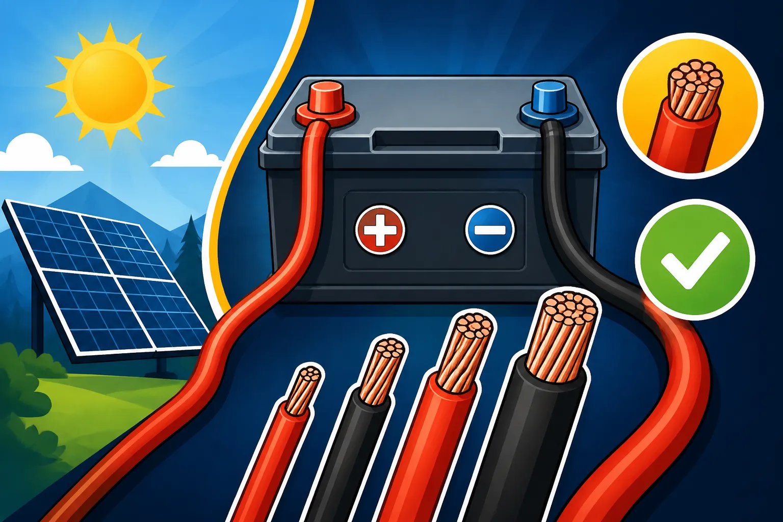
Note: AWG numbers work in reverse – smaller numbers (e.g., 4 AWG) mean thicker wire. Beyond 1 AWG, it goes to 1/0 (pronounced "one aug"), 2/0 ("two aug"), 3/0 ("three aug"), and 4/0 ("four aug"), which are progressively thicker.
Using the chart: Find your calculated amperage on the left, then move across to your measured cable length to find the recommended AWG size.
Applying Adjustments:
- Temperature Derating: If your cables will be in a very hot environment (consistently above 86°F or 30°C), consider going up one wire size from what the chart suggests.
- Bundling: If you're running multiple cables bundled tightly together in conduit, their ability to dissipate heat is reduced. You might need to increase the wire size.
- Voltage: Remember that these charts are often for 12V systems. If you're running a 24V or 48V system, your amperage will be much lower for the same wattage, allowing for thinner cables.
Step 4: Account for System Voltage and Future Expansion
This step brings everything together and adds a layer of practical foresight.
-
System Voltage Impact: As discussed, higher system voltages drastically reduce the current draw for the same power output. For instance, a 5000W inverter on a 48V system will draw roughly 104 amps at its lowest voltage (5000W / 48V = 104A). Compare this to a 12V system where that same 5000W inverter would draw around 476 amps (5000W / 10.5V = 476A). This is why a 48V system often allows you to use much thinner and more manageable 2/0 AWG or even 1/0 AWG cables, whereas a 12V system might require massive 4/0 AWG or even larger cables. If you're planning a larger off-grid setup, exploring 12V vs 24V vs 48V: Which to Choose is highly recommended to optimize cable sizing and overall cost.
-
Future Expansion: Are you building your system in phases? Do you anticipate adding more panels, more batteries, or a larger inverter down the line? If so, it's often prudent to slightly oversize your battery cables now. For example, if your current calculations suggest 2/0 AWG, but you know you'll double your inverter size in a year, jumping to 4/0 AWG now could save you a significant amount of work and cost later. It's always easier to run slightly thicker wire now than to have to tear everything apart and replace undersized cables when you How to Design an Expandable System. This foresight can prevent future headaches and ensure your system grows gracefully with your power needs.
Step 5: Proper Terminations and Connections
The cable itself is only half the story; how you connect it is equally important. A poorly terminated cable can create a bottleneck of resistance and heat, even if the cable itself is perfectly sized.
- Lugs: You'll need copper lugs that match your cable gauge (e.g., 2/0 AWG lugs for 2/0 AWG cable) and the size of the terminal (e.g., 3/8-inch ring terminal).
- Crimping: For high-current DC applications, proper hydraulic crimping is the gold standard. A good quality hydraulic crimper creates a cold-welded connection that is mechanically strong and electrically efficient. Avoid hammering lugs flat or using cheap, inadequate crimpers; these create weak, high-resistance connections that can heat up dangerously.
- Soldering: While soldering can create a good electrical connection, it's generally not recommended for high-current battery cables unless done by a very experienced hand. Solder can melt under extreme heat (e.g., short circuit) and can also make the cable rigid and prone to fatigue.
- Heat Shrink: Always use marine-grade heat shrink tubing over your crimped connections. This provides insulation, protects against corrosion, and adds strain relief, ensuring a long-lasting and safe connection.
- Cleanliness: Ensure all connection points (battery terminals, inverter terminals) are clean and free of corrosion. Use a wire brush if necessary. A tiny bit of dielectric grease on the battery terminals can help prevent future corrosion.
- Tightness: Once connected, ensure all terminals are tightened to the manufacturer's specifications. Loose connections are a major source of resistance and heat. But don't overtighten, as you could strip threads or damage terminals.
Following these steps for Off-Grid Solar Wiring Best Practices will ensure not just the right cable size, but a safe and efficient connection throughout your system.
Common Mistakes and How to Avoid Them
Even with the best intentions, it's easy to fall into common traps when sizing and installing battery cables. Being aware of these pitfalls can save you a lot of trouble and expense down the road.
Underestimating Current Draw
This is perhaps the most frequent and dangerous mistake DIYers make. Many people will calculate their average daily power usage or even the inverter's continuous rating, but they completely forget about surge currents. Many appliances, especially those with motors (like well pumps, refrigerators, air conditioners, or microwaves), draw a massive amount of current for a brief moment when they first start up. This "starting watts" or surge can be 3-7 times their continuous running watts.
If your cables are sized only for the continuous load, these brief, high-current surges can cause significant voltage drop, trigger low-voltage disconnects on your inverter or charge controller, and generate excessive heat in the cables. While the surge might be short-lived, repeated surges on undersized cables can degrade insulation, weaken connections, and prematurely wear out components. Always consider the highest peak current your inverter might ever draw, even if it's for a fraction of a second, and size your cables to handle that with a healthy margin. Understanding How to Size an Inverter for Surge Loads is key to avoiding this common pitfall.
Ignoring Voltage Drop Calculation
Another common oversight is neglecting the voltage drop calculation or using an overly generous percentage (like 5% or even 10%). While a 5% voltage drop might be acceptable for some low-priority DC circuits, it's generally too high for the main battery-to-inverter runs in an off-grid system, especially on 12V setups.
A 5% drop on a 12V system means you're losing 0.6 volts (5% of 12V). This might not sound like much, but when your battery is already at its lower operating voltage (say, 11V), losing another 0.6V means your inverter is only seeing 10.4V. Many inverters have a low-voltage cut-off around 10.5V, meaning your system will shut down prematurely, even if your batteries still have usable capacity. For 48V systems, the impact of a 1% or 2% drop is proportionally smaller, but it still means wasted energy. Always aim for a 1-2% maximum voltage drop on your main battery cables to ensure optimal performance and full utilization of your battery capacity. Remember, every little bit of voltage counts when you're off-grid.
Using Inappropriate Cable Types or Poor Quality Connectors
This goes back to the safety aspect. You might find some thick, inexpensive electrical wire at a big box hardware store and think, "Hey, this is just as good!" But not all thick wire is created equal. Standard household Romex (NM-B cable) or THHN wire is typically solid core or has a low strand count, making it rigid and prone to breaking with vibration, common in RVs, boats, or even off-grid cabins where things shift. It's also not always rated for the high-current DC applications you'll find in battery banks.
You need flexible, high-strand count copper cable, typically welding cable or marine-grade battery cable (like those from Victron Energy for instance). These cables are designed to handle high current, resist vibration, and remain flexible for easier routing. Beyond the cable, the quality of your connectors and the method of termination are vital. Cheap, thin lugs or improper crimping methods (like using pliers or a hammer) create high-resistance points that heat up, corrode, and can eventually fail, potentially causing a fire. Invest in good quality copper lugs and a proper hydraulic crimper. It’s a tool you’ll use for years, and the peace of mind it provides is priceless. Don't cut corners on the things that carry all your power; it's simply not worth the risk.
Disclaimer
The information provided in this guide is for general informational purposes only and does not constitute professional electrical advice. Working with high-voltage DC systems can be dangerous. Always consult with a qualified electrician or solar professional to ensure your off-grid solar system is designed, sized, and installed safely and in compliance with all local codes and regulations.