How to Wire an Inverter Charger
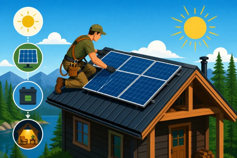
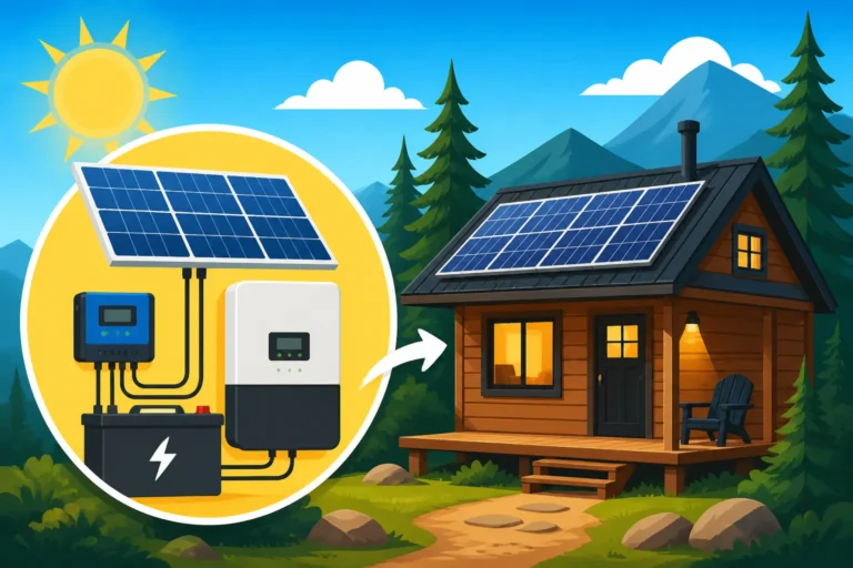
Wiring an inverter charger can feel like staring at a spaghetti bowl of cables and connectors, especially when you’re building out your off-grid solar system. It’s a critical component that bridges your battery bank, your solar charge controller, and your home's electrical panel, not to mention external power sources like a generator. The good news is, while it looks intimidating, it's a manageable task with the right guidance and a meticulous approach. This comprehensive guide will walk you through the process, ensuring your off-grid power setup is safe, efficient, and reliable.
Understanding Your Inverter Charger and Its Role
Before you even think about grabbing a wrench, it's crucial to understand what an inverter charger is and how it functions within your off-grid ecosystem. This isn't just a simple device; it's the brain and muscle behind turning raw battery power into usable electricity for your appliances and vice-versa.
What an Inverter Charger Does
Think of an inverter charger as a multi-talented superhero for your power system. Its primary role, as an inverter, is to transform the direct current (DC) stored in your batteries into alternating current (AC) that powers most of your household appliances, lights, and electronics. Without an inverter, your microwave, refrigerator, or even your laptop charger simply wouldn't work on battery power. This DC to AC conversion is fundamental to off-grid living, allowing you to use standard residential appliances far from the utility grid.
But it doesn't stop there! The "charger" part of its name is equally important. When you have an external AC power source available – maybe you've got a generator running on a cloudy day, or you're temporarily hooked up to shore power at an RV park – the inverter charger takes that AC power and converts it back into DC to replenish your battery bank. This intelligent charging capability means you're not just relying on your solar panels; you have a robust system that can utilize multiple sources to keep your batteries topped up. Many modern inverter chargers are also adept at managing power flow, prioritizing solar, then charging from an AC source, and automatically switching to inverter mode when external AC is unavailable, providing a seamless power experience.
Key Components and Connections
An inverter charger, while complex internally, has several distinct connection points that you'll need to understand for proper wiring. Knowing these helps demystify the installation process.
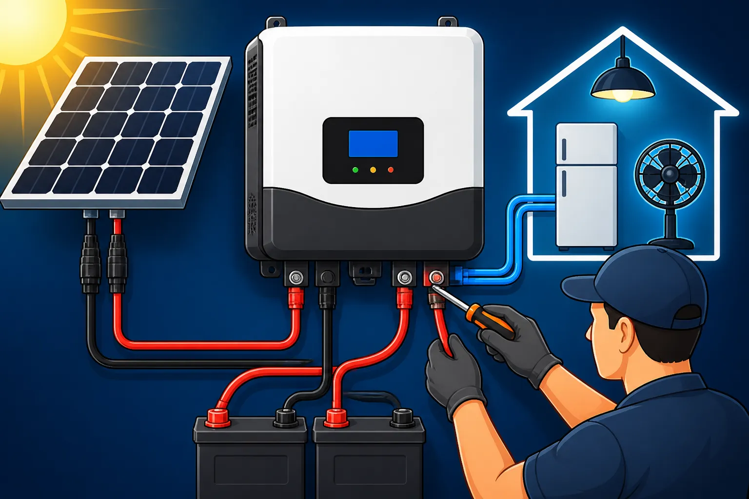
First, you'll have the DC Input terminals. These are usually large, robust terminals, often marked with (+) and (-) for positive and negative, respectively. These are where your hefty battery cables will connect, drawing power directly from your battery bank. Getting the polarity right here is absolutely critical – reversing it can cause serious damage to your inverter and batteries. These terminals are designed to handle significant current, which is why the cables connected here need to be appropriately sized.
Next, you’ll find the AC Input terminals. This is where you'll connect an external AC power source, like your generator or a shore power connection. Some inverter chargers have a single AC input, while others might have multiple inputs for different sources, sometimes referred to as "generator input" or "utility input." This is the pathway for external AC power to either pass through directly to your loads (bypassing the inverter function) or be converted to DC to charge your batteries.
Then there are the AC Output terminals. These are the connections that deliver the converted AC power (either from your batteries via the inverter or directly from the AC input source when available) to your home's electrical panel or load center. This is the power that will run your lights, appliances, and everything else in your off-grid setup.
Lastly, you'll always find a grounding lug or terminal. This is a non-negotiable safety feature, connecting the chassis of your inverter charger to your system's main ground. Proper grounding is paramount for protecting against electrical shocks and ensuring your system operates safely, especially in the event of a fault. Many inverter chargers also feature remote control ports or data communication ports, often small RJ45 or USB connections, which allow you to connect a dedicated display, a computer, or even an app on your phone for monitoring and controlling the unit, which is incredibly handy for tracking performance and adjusting settings. Companies like Renogy and Victron Energy offer robust monitoring solutions for their inverter chargers.
Essential Safety Measures Before You Begin Wiring
Working with electricity, especially high-voltage or high-amperage systems like off-grid solar, demands an unwavering commitment to safety. Skipping these crucial steps isn't just risky; it could be deadly or lead to costly damage to your equipment.
Disconnecting All Power Sources
Before you touch any wire or terminal, the absolute first step is to disconnect all power sources. This isn't just about flipping a switch; it's about physically isolating your inverter charger from any potential current. This means disconnecting your battery bank, turning off your solar array (usually done via a DC disconnect or by covering the panels), ensuring any generator is off and unplugged, and if applicable, disconnecting from shore power. You want to make absolutely sure there is no way for electricity to flow into or out of the inverter charger while you're working on it.
Always assume wires are live until you've verified they are not with a multimeter. Even a small residual charge in a capacitor can give you a nasty surprise. Wear appropriate personal protective equipment (PPE): insulated gloves, safety glasses, and non-conductive shoes. Keep a fire extinguisher (Class C, suitable for electrical fires) nearby, just in case. It might sound overly cautious, but remember, once a system is wired, mistakes can be difficult and dangerous to rectify. This initial disconnection phase is the most critical safety step you'll take. For a deeper dive into safe practices, consider reviewing resources on how to install an off-grid solar system.
Proper Wire Sizing and Overcurrent Protection
Choosing the correct wire gauge and installing appropriate overcurrent protection devices (like fuses and circuit breakers) are not optional; they are fundamental to the safety and efficiency of your off-grid system. Undersized wires can overheat, melt insulation, and cause fires, while inadequate fusing leaves your expensive equipment vulnerable to damage from surges or short circuits.
The National Electrical Code (NEC) provides guidelines for wire sizing based on the current (amperage) it will carry, the voltage drop over distance, and the wire's insulation type. For your DC battery cables, which carry very high currents, you'll often need extremely thick gauges – sometimes as large as 2/0 or 4/0 AWG, depending on your system voltage and inverter size. The longer the cable run, the thicker the wire needs to be to minimize voltage drop, which can impact performance and efficiency. An undersized cable might restrict the current flow to your inverter, leading to reduced output and unnecessary heat. You can find detailed calculators online or refer to your inverter charger's manual for specific recommendations. For more information on this, check out our guide on How to Size Wire and Cables.
Overcurrent protection is your system's guardian angel. Fuses or circuit breakers must be installed on both the DC side (between your batteries and the inverter charger) and the AC side (on both the input from a generator/shore power and the output to your load center). On the DC side, the fuse or breaker should be located as close to the battery bank as safely possible – typically within 7 inches of the battery terminal. This protects the cable run itself from short circuits. On the AC side, standard circuit breakers in an electrical panel protect your wiring and equipment. Always choose fuses and breakers rated slightly above the continuous operating current of the circuit, but below the maximum current the wire can safely handle. Your inverter charger's manual will specify the recommended fuse and breaker sizes for its various connections. Neglecting proper overcurrent protection is one of the most common and dangerous mistakes in off-grid wiring. Our article on How to Size Fuses and Breakers offers more insights into this critical aspect.
Step-by-Step Wiring Guide for Your Off-Grid Inverter Charger
Alright, with safety firmly in mind and your components ready, let's get down to the actual wiring. Taking it one connection at a time will help keep things clear and prevent errors. Remember, precision and patience are your best friends here.
Connecting to the Battery Bank
This is arguably the most critical connection, as your battery bank is the heart of your off-grid system, and the inverter charger needs a robust connection to draw power.
First, ensure your battery bank is fully assembled and properly wired, whether it's a 12V, 24V, or 48V system. If you're unsure about this, refer to our guide on How to Wire a Battery Bank. You'll need high-quality, heavy-gauge battery cables with appropriately sized lugs crimped onto the ends. As discussed, the gauge depends heavily on your inverter's power rating and your system's voltage – higher voltage systems (like 48V) draw less current for the same power, so they can use thinner cables than 12V systems. Always aim for the shortest possible cable runs between your batteries and the inverter to minimize voltage drop and maximize efficiency.
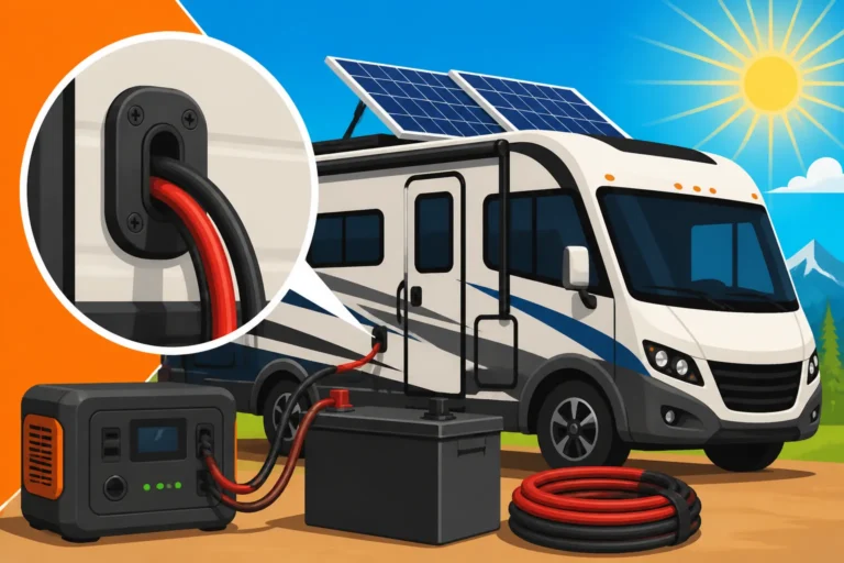
Connect the positive (+) terminal of your battery bank to the positive (+) DC input terminal on your inverter charger. Similarly, connect the negative (-) terminal of your battery bank to the negative (-) DC input terminal on your inverter charger. Double-check your polarity multiple times before tightening anything down. A fuse or DC-rated circuit breaker must be installed on the positive cable within a very short distance of the battery bank (typically 7 inches or less). This protects against a short circuit in the cable itself. Ensure all connections are clean, tight, and secure. Loose connections can lead to resistance, heat buildup, and power loss.
Wiring the AC Input Source (Generator or Shore Power)
Your inverter charger's ability to charge your batteries from an external AC source like a generator or utility grid (if you have a hybrid setup) is a huge advantage. This connection allows your system to be resilient even when solar output is low.
Locate the AC input terminals on your inverter charger. These are typically labeled "AC In" or "Generator In." You'll connect your generator or shore power input to these terminals. This usually involves three wires: Line (Hot), Neutral, and Ground. Ensure you correctly identify which wire goes to which terminal according to your inverter charger's manual and the wiring standards of your region. For instance, in North America, Line is typically black or red, Neutral is white, and Ground is green or bare copper.
If your inverter charger doesn't have an integrated transfer switch, you'll need an external one to safely switch between your inverter's output and an external AC source. Many modern inverter chargers, especially higher-end models like those from Victron Energy or Sol-Ark, have sophisticated internal transfer switches that automatically sense the presence of an AC input and seamlessly switch loads and begin charging batteries. Always ensure the AC input circuit has appropriate overcurrent protection (a circuit breaker) at the source (e.g., on your generator's output or at the shore power pedestal). This protects your wiring and inverter from potential overloads or faults from the external AC source. Remember that the size of the AC input breaker should match the input current rating of your inverter charger.
Connecting to the AC Output Load Center
This is where your inverter charger truly delivers, supplying AC power to your home or vehicle's electrical system.
Find the AC output terminals, usually labeled "AC Out" or "Load." These connections will go to your main electrical panel or a sub-panel in your off-grid dwelling. Similar to the AC input, you'll connect Line (Hot), Neutral, and Ground wires. The Line wire from the inverter's AC output goes to a breaker in your load center. The Neutral from the inverter's AC output connects to the neutral bus bar in your panel, and the Ground connects to the ground bus bar.
It's absolutely essential that the neutral and ground are properly managed. In an off-grid system where the inverter is the sole source of AC power, the neutral and ground are typically bonded (connected) at the inverter or at the first disconnect point downstream from the inverter. However, if you are also receiving AC from a generator or shore power, it is critical to ensure that there is only one neutral-to-ground bond in your entire AC system. If your inverter handles the bonding internally when acting as the sole source, it might disconnect this bond when an external AC source (which has its own bond) is present. Consult your inverter charger's manual and relevant electrical codes (like the NEC for US installations) for precise guidance on neutral-to-ground bonding in your specific setup. Proper bonding prevents dangerous ground loops and ensures safety devices like ground fault circuit interrupters (GFCIs) function correctly.
Grounding and Bonding
We've touched on it already, but grounding and bonding are so critical they deserve their own dedicated section. This isn't just about code compliance; it's about life safety.
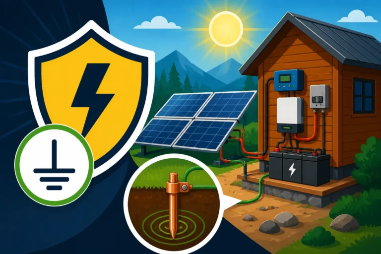
Grounding refers to connecting your electrical system to the earth. For an off-grid system, this typically means driving one or more ground rods deep into the soil and connecting them to your system's main ground bus bar or directly to the inverter's chassis ground lug with a heavy gauge bare copper wire. This provides a safe path for fault currents to dissipate into the earth, preventing dangerous voltage buildup on metallic enclosures and reducing the risk of electric shock. Every major component in your system – solar array frames, inverter chassis, battery enclosures (if metallic), and your electrical panel – should be connected to this common ground.
Bonding refers to connecting all non-current-carrying metallic parts of your electrical system together to create a continuous, low-impedance path to ground. This ensures that if a live wire accidentally touches a metallic enclosure, the entire enclosure becomes energized to the same potential, preventing a voltage difference that could shock someone. This also helps fault currents flow quickly enough to trip a breaker or blow a fuse. The inverter charger's chassis ground lug must be connected to your system's main ground. This is usually done with a green insulated or bare copper wire. For detailed instructions on this vital step, refer to our article on How to Ground an Off-Grid Solar System. Do not skimp on proper grounding and bonding; it is your primary defense against electrical hazards.
Testing Your Inverter Charger System
Once all the wires are connected, fuses are in place, and everything looks tidy, it's time for the moment of truth. Testing your system methodically is key to ensuring everything works as expected and to catch any issues before they become serious problems.
Initial Power-Up and Monitoring
Before applying full power, do one final visual inspection. Check every single connection point: Are the battery terminals tight? Are the AC wires correctly seated? Is the ground wire securely attached? Once you're confident, you can begin the power-up sequence.
The general rule is to connect the battery bank first. Flip your DC disconnect switch or connect your battery cables. Your inverter charger should power up and display its status – typically showing battery voltage and perhaps some error codes if something isn't right. Watch for any unusual lights, smells, or sounds. Next, if you have solar, activate your solar array (uncover panels, close DC disconnects between panels and charge controller). The charge controller should begin regulating power to the batteries. Finally, introduce your AC input source (generator or shore power). Observe how the inverter charger handles this; it should ideally switch to "pass-through" mode (running loads directly from the AC source) and begin charging your batteries. Many inverter chargers from brands like Renogy or Victron will have clear displays or indicators showing charging status and power flow.
At this stage, you're looking for normal operation, no warning lights, and the correct readings on your display or monitoring app. Pay close attention to battery voltage, AC output voltage (should be stable, e.g., 120V or 240V AC), and charging current.
Load Testing and Troubleshooting Common Issues
Once the inverter charger appears to be operating normally, it's time to test it under load. Don't just plug in everything at once. Start with small, non-critical loads, like a few LED lights or a phone charger. Observe how the system reacts. Does the battery voltage drop significantly? Does the inverter show any strain?
Gradually increase the load by adding more appliances. A common practice is to start with resistive loads (like a toaster or a hairdryer for a brief moment, if your system can handle it) to test the inverter's capacity, then move to inductive loads (like a refrigerator or a well pump, which have high surge demands). Pay attention to the inverter charger's fan; it should kick on when it starts to work hard. Keep a close eye on your battery monitor (a good quality monitor like a Victron SmartShunt is invaluable here) to understand how your battery bank is performing under various loads. This is also a good opportunity to learn How to Size an Off-Grid Inverter for your specific load requirements.
If you encounter issues, here are some common troubleshooting starting points:
- No Power/No Display: Check battery connections, DC fuses, and the main DC breaker. Ensure the battery bank has sufficient charge.
- Overload Warning: You're asking for too much power. Disconnect some loads immediately. Check your appliance wattages against your inverter's continuous and surge ratings.
- Low Voltage Disconnect: Your batteries are running too low. The inverter is protecting them. Reduce loads or charge batteries.
- Ground Fault: This often indicates a short to ground somewhere in your AC wiring. Immediately disconnect power and carefully inspect all AC connections and appliances.
- AC Input Not Recognized: Check the AC input breaker, cables, and ensure the generator/shore power is providing stable voltage.
- No Charging from AC Input: Verify AC input settings on the inverter charger, ensure the AC input breaker is on, and check the generator's output.
Many modern inverter chargers have diagnostic codes displayed on their screens or accessible via their monitoring apps. Consult your manual to decipher these codes and follow the recommended troubleshooting steps.
Advanced Considerations and Best Practices
Going off-grid is a journey, not a destination. As you become more comfortable with your system, you'll likely want to optimize it further, integrate more components, and ensure its longevity.
Integrating with Solar Charge Controllers
While your inverter charger handles the AC side of battery charging from a generator or shore power, your solar panels rely on a dedicated solar charge controller to efficiently and safely charge your batteries from the sun. It's important to understand that these are usually separate components, even if they're part of the same overall off-grid ecosystem.
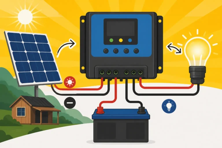
The solar charge controller (often an MPPT controller for maximum efficiency) connects your solar panels directly to your battery bank. Its job is to regulate the voltage and current from the panels to prevent overcharging and ensure the batteries are charged optimally. The inverter charger then draws power from this same battery bank. In many systems, the charge controller will have its own display or monitoring system. While they are separate, modern inverter chargers and charge controllers (especially from the same brand like a complete Renogy setup or a Victron system) can often communicate with each other. This allows for a more holistic view of your power system, where you can see total energy production, consumption, and battery state of charge from a single interface. When setting up your system, ensure the battery charging parameters (like bulk, absorb, and float voltages) are consistent between your solar charge controller and your inverter charger's battery charger settings to avoid conflicting charging profiles that could harm your batteries. For a deeper dive into wiring this component, check out our guide on How to Connect a Charge Controller.
Monitoring and Remote Management
Once your inverter charger is wired up and running, monitoring its performance becomes incredibly useful. You're no longer just guessing how much power you're using or how full your batteries are. Modern off-grid systems offer sophisticated monitoring capabilities that can transform your off-grid living experience.
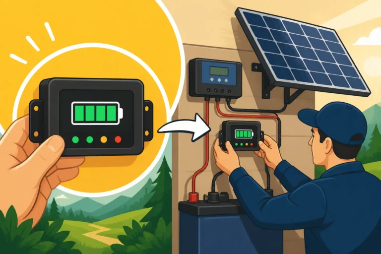
Many inverter chargers come with a basic LCD screen that displays real-time data like battery voltage, AC input/output, and charging/inverting status. However, for a truly comprehensive overview, dedicated battery monitors are invaluable. Devices like the Victron SmartShunt or the Renogy shunt-based battery monitor connect directly to your battery bank and provide highly accurate readings of state of charge, current draw, remaining runtime, and historical data. These often connect via Bluetooth to a smartphone app, giving you detailed insights into your system's health from anywhere.
For even more advanced setups, some inverter chargers offer internet connectivity or dedicated communication hubs that allow for remote monitoring and even control over the internet. Imagine being able to check your battery level or start your generator remotely from your phone while you're away from your cabin! This level of insight allows you to optimize your energy consumption, identify potential issues early, and ensure your system is running at peak efficiency. Understanding How to Install a Battery Monitor is a great next step for gaining this kind of control.
Future Expansion and Maintenance
An off-grid solar system isn't a "set it and forget it" proposition. Like any complex piece of equipment, it requires ongoing maintenance and, over time, you might find yourself wanting to expand it.
Maintenance involves routine checks of all connections for tightness and corrosion, inspecting cables for wear and tear, and ensuring ventilation around your inverter charger is unobstructed. Keep the unit clean and free of dust. Your batteries, especially if they're lead-acid, will require specific maintenance (like checking water levels), but even LiFePO4 batteries benefit from periodic inspections. Staying proactive with maintenance can significantly extend the lifespan of your components and prevent costly breakdowns. Our detailed Off-Grid Solar Maintenance Guide can provide you with a comprehensive checklist.
Future Expansion is a common desire as off-gridders learn more about their energy needs. When designing and wiring your initial system, it's wise to plan for potential expansion. This might mean installing a slightly larger electrical panel than immediately necessary, running conduit with extra capacity, or choosing an inverter charger that can be paralleled with another unit in the future to increase your overall power output. Selecting components from reputable brands known for system integration, such as Victron Energy or Sol-Ark, can make future upgrades much smoother. While it might add a little cost upfront, thinking about how your system might grow can save you a lot of headache and expense down the road when you realize you want to add more panels, more batteries, or another high-demand appliance. For those just starting out, taking the time to learn the ins and outs of your initial build, perhaps following a DIY Off-Grid Solar Installation Step by Step guide, will set you up for success when you decide to grow your power system.
Disclaimer
The information provided in this guide is for educational and informational purposes only and is not intended as professional electrical advice. Working with electricity can be dangerous. Always consult with a qualified electrician or solar professional before installing or modifying any electrical system. Follow all local and national electrical codes and safety regulations. The author and publisher are not liable for any injury, damage, or loss resulting from the use or misuse of this information.