How to Wire Solar Panels in Parallel
Stepping into the world of off-grid solar can feel like learning a whole new language, especially when terms like "series" and "parallel" wiring start flying around. It's totally understandable to feel a bit overwhelmed trying to figure out the best way to connect your precious solar panels to get the most out of them. Many folks get stuck wondering how to get enough power to run their beloved appliances without overcomplicating things or, worse, damaging their system. This comprehensive guide is here to demystify parallel wiring, showing you exactly how and when to use it to optimize your off-grid solar setup for maximum efficiency and reliability.
Understanding the Fundamentals of Parallel Solar Wiring
When you're building an off-grid solar system, one of the first big decisions you'll face is how to connect your solar panels. It's not just about pointing them at the sun; it's about making sure the electricity they generate flows correctly to your battery bank and inverter. Parallel wiring is one of the two primary methods, and it's essential to grasp its principles before you start hooking anything up.
What Parallel Wiring Means for Your Solar Array
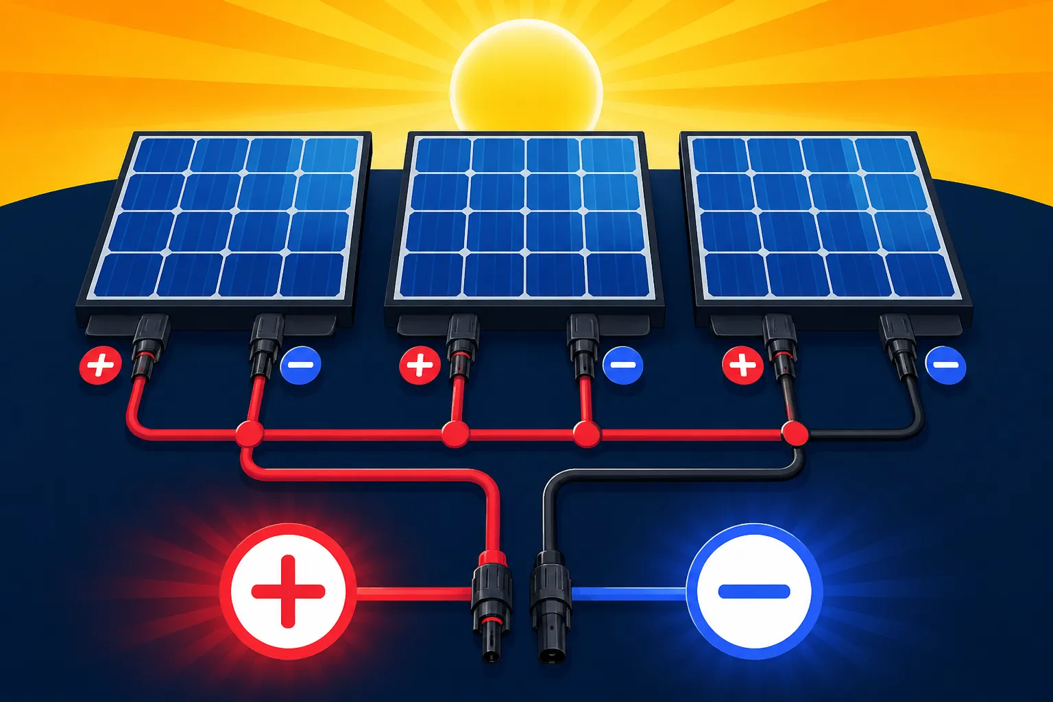
In a nutshell, wiring solar panels in parallel means you're connecting the positive terminal of one panel to the positive terminal of the next, and the negative terminal of one panel to the negative terminal of the next. Think of it like a highway with multiple lanes all going in the same direction. Each panel acts as a separate "lane" contributing current, but the "speed limit" (voltage) stays consistent across all of them. This setup is fundamentally different from series wiring, where panels are connected end-to-end, adding their voltages together while maintaining the same current.
The key takeaway here is that parallel connections will keep the system voltage the same as that of a single panel (or the lowest voltage panel in the array, if there's a mismatch), but it will add up the amperage (current) from each panel. So, if you have two 12V, 10-amp panels, wiring them in parallel will give you a combined output of 12V and 20 amps. This is incredibly useful for specific applications, especially when dealing with lower voltage battery banks, like a 12V system in an RV or a small cabin.
Why Parallel Wiring is Often the Go-To Choice
Many off-grid enthusiasts, especially those starting with smaller setups, gravitate towards parallel wiring for several compelling reasons. The main driver is often the need to match the voltage requirements of their existing battery bank or charge controller. If you have a 12V battery bank, you typically want your solar array's voltage to be compatible, usually around 18-20V (Voc – open-circuit voltage) for a nominal 12V panel to ensure efficient charging through an MPPT charge controller. Wiring panels in parallel keeps your voltage within that range while increasing the total current available for charging.
Another significant advantage is its resilience to partial shading. Imagine a tree branch casts a shadow over just one of your panels. If your panels were wired in series, that one shaded panel could significantly reduce the output of the entire array, acting like a bottleneck. However, in a parallel configuration, the shaded panel will still reduce its own output, but the other, unshaded panels can continue producing at their full capacity. This means your overall system performance is less impacted by localized shading, which can be a real blessing if you have trees or other obstructions around your installation site. This consideration is a big part of designing an optimal system, as discussed in detail in our guide on How to Design an Off-Grid Solar System Step by Step.
When to Opt for Parallel Connections in Your Off-Grid System
Deciding between parallel, series, or a combination of both is a critical design choice that impacts your system's efficiency, cost, and performance. Parallel wiring shines in specific scenarios, making it the preferred method for many off-grid applications.
Matching Lower Voltage Battery Banks
The most common reason to wire your solar panels in parallel is to match the voltage of a lower-voltage battery bank, typically 12V or 24V. Let's say you have a 12V battery bank in your camper van or a small hunting cabin. If you used two 12V nominal solar panels and wired them in series, your combined voltage would be around 36-40V (open-circuit), which is too high for a standard 12V battery without a special high-voltage input charge controller. By wiring them in parallel, your array voltage remains within the appropriate range for a 12V system while doubling the available charging current.
This is crucial because your charge controller needs to see a voltage from the solar panels that is higher than your battery bank's voltage to effectively push charge into the batteries. However, if the panel voltage gets too high, some charge controllers (especially PWM types) become inefficient, or the voltage might exceed the controller's maximum input, potentially damaging it. For systems aiming for lower voltage operation, understanding How Many Batteries for an Off-Grid System is key, as battery voltage often dictates panel wiring strategy.
Mitigating the Effects of Partial Shading
As we touched on earlier, partial shading is a real headache for solar arrays, especially if you live in an area with lots of trees or if your panels might get covered by leaves or debris. In a series-wired string, if even one cell in one panel is shaded, the entire string's output can plummet because the shaded cell acts like a resistor, choking the flow of current for the whole circuit. This is known as the "Christmas light effect" – if one light goes out, the whole string might dim or go out.
With parallel wiring, the impact of shading is significantly reduced. Each panel essentially operates independently in terms of current production. So, if one panel is partially shaded and its current output drops, the other panels in the parallel array continue to produce power at their full current rating. While you'll still lose the power from the shaded portion of the array, the unshaded panels won't be dragged down by their struggling neighbors. This makes parallel wiring particularly attractive for installations where some level of shading is unavoidable, or for situations like RVs where parking spots might have varying sun exposure throughout the day.
Optimizing for Smaller Systems and Expandability
For those just starting their off-grid journey or powering smaller loads like those in a tiny home or a shed, parallel wiring can be simpler and more forgiving. Many beginner-friendly solar kits, like those from Renogy, are designed with parallel connections in mind, especially for 12V systems. They often come with the necessary MC4 branch connectors, making the process straightforward.
Moreover, parallel wiring can offer better flexibility for future expansion. If you decide you need more power down the line, adding another panel in parallel is often a simpler process than reconfiguring a complex series string, assuming your charge controller can handle the increased amperage. You can easily add more current capacity to your system by just adding another parallel leg, without needing to completely redesign your array's voltage profile. This incremental approach can also help manage the Cost of Expanding an Off-Grid System over time.
Essential Components for Parallel Solar Panel Wiring
Before you start connecting anything, it’s vital to have the right tools and components on hand. Using high-quality, appropriately sized equipment isn't just about efficiency; it's about safety and the longevity of your entire off-grid system. Cutting corners here can lead to costly repairs or even dangerous electrical hazards.
MC4 Branch Connectors and Proper Cabling
The cornerstone of parallel solar panel wiring is the MC4 branch connector, often called a "Y-splitter." These connectors allow you to combine the positive leads from multiple panels into a single positive output cable, and similarly for the negative leads. They come in various configurations, typically 2-to-1, 3-to-1, or 4-to-1, meaning they can combine the output of two, three, or four panels, respectively. When shopping for these, always look for reputable brands and ensure they are UV-resistant and waterproof for outdoor use. Many quality kits, including those you might find on Amazon, will include these.
Just as important as the connectors themselves is the cabling. You'll need specialized solar PV cable, which is designed to withstand harsh outdoor elements, including UV radiation and extreme temperatures. The gauge of your wire is crucial and depends on the total current your array will produce and the distance to your charge controller. Using wire that is too thin can lead to significant voltage drop, wasting power and potentially causing overheating. Our guide on How to Size Wire and Cables provides a detailed breakdown of how to calculate the correct gauge for your setup. For short runs, you might get away with 10 AWG or 12 AWG, but longer distances or higher current often demand thicker cables like 8 AWG or even 6 AWG.
Fuses, Breakers, and Disconnects
Electrical safety is paramount in any solar installation. Fuses and breakers are non-negotiable components that protect your equipment and prevent fires in the event of a short circuit or overcurrent. For parallel-wired arrays, you'll need to consider overcurrent protection for each individual panel string if the reverse current potential exceeds the panel's maximum series fuse rating (which is typically the case when combining multiple parallel strings). Generally, you'll want an appropriately sized DC breaker or fuse between your solar array and your charge controller.
The sizing of these protective devices is critical. A general rule of thumb for fuses is to size them at 125% of your expected maximum continuous current. For instance, if your parallel array produces a maximum of 30 amps, you'd want a 40-amp fuse or breaker. Additionally, a DC disconnect switch installed between your solar array and charge controller is essential. This allows you to safely de-energize the system for maintenance, troubleshooting, or in an emergency, as detailed in our guide on Off-Grid Solar Safety and Grounding. These aren't just recommendations; they're vital safeguards for your system and your peace of mind.
Monitoring Tools and Battery Considerations
While not strictly part of the "wiring" process, having a reliable multimeter is absolutely indispensable. You'll use it to check voltages and currents at various points during and after installation, ensuring everything is working as expected and helping you troubleshoot any issues. A good quality digital multimeter will be your best friend.
Beyond the panels, don't forget the rest of your system. Your battery bank's voltage and capacity are the primary factors dictating your panel wiring. If you're using a 12V battery bank, parallel panels are often the natural choice. For 24V or 48V systems, you might use a combination of series and parallel wiring to achieve the desired voltage and current. Understanding how to wire a battery bank correctly is just as important, especially when you're aiming for optimal charging and discharge cycles. The selection of your charge controller, whether it's an MPPT or PWM, also heavily influences your optimal panel configuration. Our article on How to Choose an Off-Grid Charge Controller provides more insights into this critical component.
Step-by-Step Guide to Wiring Solar Panels in Parallel
Now that we've covered the "why" and the "what," let's get down to the "how." Wiring solar panels in parallel is a relatively straightforward process, but it requires careful attention to detail and a commitment to safety. Take your time, double-check your connections, and always prioritize safety over speed.
Planning Your Array and Gathering Materials
Before you even touch a wire, a little planning goes a long way. Start by sketching out your solar array. How many panels do you have? Where will they be mounted? What is the nominal voltage and maximum current (Imp) of each panel? Knowing these details will help you determine how many branch connectors you'll need and the appropriate gauge for your cabling. For example, if you have four 100W, 12V panels (each producing roughly 5.5 amps), wiring them in parallel will give you a total of 12V nominal and about 22 amps (4 x 5.5A).
Next, gather all your materials:
- Solar panels (with MC4 connectors)
- MC4 branch connectors (Y-splitters) – ensure you have enough for your configuration (e.g., three 2-to-1 connectors for four panels).
- Solar PV cable (correct gauge and length)
- MC4 crimping tool (if making your own cables)
- Wire cutters/strippers
- DC disconnect switch
- DC fuses or breakers
- Multimeter
- Personal protective equipment (PPE): safety glasses, gloves.
Remember, quality components, even for something as simple as a connector, can make a huge difference in system reliability. Many DIY builders find good value in kits from brands like Renogy, which often include many of these essential components.
Making the Physical Connections
Alright, let's get wiring!
- Safety First: ALWAYS ensure your solar panels are covered or facedown before making any electrical connections. Even in low light, they can produce voltage. Wearing insulated gloves and safety glasses is a wise precaution.
- Identify Terminals: Each solar panel will have two MC4 cables, one ending in a male connector (+) and one in a female connector (-).
- Connect in Parallel:
- Take your first MC4 branch connector (e.g., a 2-to-1 type for two panels).
- Connect the positive male connector from Panel 1 to one of the positive female inputs on the branch connector.
- Connect the positive male connector from Panel 2 to the other positive female input on the same branch connector.
- Repeat this process for the negative terminals, connecting the negative female connector from Panel 1 to a negative male input on a second branch connector, and the negative female connector from Panel 2 to the other negative male input.
- If you have more than two panels, you'll continue this pattern. For instance, with four panels, you'd make two sets of parallel connections (Panel 1+2, Panel 3+4), then use another set of branch connectors to combine those two parallel strings. This concept of combining multiple strings is key to understanding How to Wire an Off-Grid Solar System for larger installations.
- Create Output Cables: From your final positive branch connector, you'll have one male MC4 output. From your final negative branch connector, you'll have one female MC4 output. These are your main array output cables that will run to your charge controller. Ensure these cables are the correct gauge and length, properly terminated with MC4 connectors if you're making them yourself.
Testing Your Parallel Array Output
Before you connect your array to your charge controller or battery bank, it's crucial to test its output to ensure everything is connected correctly and safely. This step can save you a lot of headaches (and potentially damaged equipment) down the line.
- Measure Open Circuit Voltage (Voc): With the panels still covered or facedown (or, if uncovered, ensure the positive and negative output cables are not connected to anything), use your multimeter to measure the voltage between the main positive and negative output cables of your parallel array. You should read a voltage roughly equivalent to a single solar panel's open-circuit voltage (e.g., around 18-22V for a nominal 12V panel). If you read a much higher voltage (e.g., double), you likely have a series connection somewhere you shouldn't. If you read 0V, check all your connections.
- Measure Short Circuit Current (Isc): This test is a bit trickier and requires a multimeter capable of measuring higher DC amperage. Carefully uncover your panels. Connect your multimeter (set to DC Amps) between the positive and negative output cables. You should read a current that is approximately the sum of the short-circuit currents (Isc) of all your panels. For example, if each panel has an Isc of 6 amps, and you have four panels in parallel, you should read around 24 amps. This is a "short circuit" test, so perform it quickly to avoid heat buildup in the cables, and ensure your multimeter can handle the current.
- Verify Polarity: Double-check that your positive output cable is indeed positive and your negative is negative. Accidentally reversing polarity when connecting to your charge controller can cause damage.
Once you've confirmed that your voltage and current readings are correct and match your expectations, you're ready to proceed with connecting your array to the rest of your system, specifically through your DC disconnect and then to your charge controller.
Safety Considerations and Best Practices for Parallel Wiring
Working with electricity, especially solar electricity, demands respect and adherence to safety protocols. A properly wired system is not just efficient; it's safe. Ignoring these considerations can lead to severe equipment damage, electrical fires, or even personal injury.
Personal Protective Equipment and Disconnecting Power
Before you begin any wiring, always don the appropriate personal protective equipment (PPE). This includes insulated gloves, which protect against electrical shocks, and safety glasses to shield your eyes from potential arc flashes or debris. While solar panels might not seem intimidating, they generate direct current (DC) electricity, which can be far more dangerous than AC due to its constant nature, making it harder for the body to let go if shocked.
The most critical safety practice is to always disconnect or cover your solar panels before working on the wiring. Solar panels produce electricity whenever light hits them, even on cloudy days. You cannot simply "turn them off" like an AC appliance. Covering them with an opaque tarp or cardboard, or placing them face down, will prevent them from generating power, rendering the connections safe to handle. Furthermore, ensure any battery banks or inverters are also disconnected to avoid backfeeding current or accidental shorts. Think of it like our guide on Off-Grid Solar Installation Guide advises: plan for safety from the very first step.
Proper Fusing, Grounding, and Overcurrent Protection
We mentioned fuses and breakers earlier, but it bears repeating: these are your system's guardians. Every major circuit path, especially the line coming from your solar array to your charge controller, absolutely needs overcurrent protection. This protects against surges, short circuits, and faults that could otherwise fry your equipment or, worse, start a fire. The National Electric Code (NEC) provides strict guidelines for solar installations, even off-grid ones. While specific local codes might vary, generally you'll need fuses or breakers sized to protect the wiring and components based on the maximum current they will carry.
Grounding is another non-negotiable safety measure. All metal components of your solar array, including panel frames and mounting racks, must be properly grounded to prevent electrical shock hazards. In the event of an electrical fault or lightning strike, proper grounding provides a safe path for electricity to dissipate into the earth, protecting both people and equipment. Failing to ground your system correctly is one of the Common Off-Grid Wiring Mistakes that can have severe consequences.
Cable Management and Weatherproofing
Your solar array and its associated wiring will be exposed to the elements 24/7. This means everything needs to be meticulously weatherproofed and securely managed. UV radiation, rain, snow, and extreme temperatures can degrade standard electrical components quickly.
- Cable Management: All cables should be neatly routed, secured with UV-resistant cable ties or clips, and protected from abrasion. Avoid leaving cables dangling or lying on sharp edges. Use conduit where appropriate, especially for runs that might be exposed to physical damage or pest intrusion.
- Weatherproofing Connections: Ensure all MC4 connections are fully seated and tight. While MC4 connectors are designed to be weatherproof, adding dielectric grease can offer an extra layer of protection against moisture intrusion in very damp environments. For any penetrations into your building or vehicle (like an RV or cabin), use proper cable entry glands or sealants to prevent water leaks. These small details ensure the longevity and reliability of your system for years to come.
Troubleshooting Common Parallel Wiring Issues
Even with the best planning and careful execution, sometimes things don't go exactly as expected. Troubleshooting is a normal part of any DIY off-grid project. The good news is that many common issues with parallel-wired solar panels have straightforward solutions if you know what to look for.
Low Voltage or Current Readings
This is perhaps the most common frustration. You've hooked everything up, eagerly checked your charge controller or multimeter, and the numbers just aren't adding up to what you calculated.
- Check Panel Coverage: First, ensure all your panels are fully exposed to direct sunlight and free from any shading. Even a small shadow on one panel can significantly impact its individual output, and thus the total current if that panel's contribution is significantly reduced.
- Verify All Connections: A loose MC4 connector or a poorly crimped wire can lead to high resistance, reducing current flow. Systematically go through each positive and negative connection point, gently tugging on cables to ensure they are secure. Pay special attention to the MC4 branch connectors themselves; sometimes, they don't fully click into place.
- Multimeter Diagnostics:
- Voltage: Measure the open-circuit voltage (Voc) of each individual panel. They should all be roughly the same. Then measure the Voc of the entire parallel array. It should match a single panel's Voc. If one panel has a significantly lower Voc, it might be faulty or heavily shaded.
- Current: With the panels uncovered, measure the short-circuit current (Isc) of each individual panel (if your multimeter can handle it). Then measure the Isc of the entire array. The array's Isc should be the sum of the individual panels' Isc. If it's much lower, you likely have a poor connection or a faulty panel. For accurate current measurements, especially on larger arrays, a DC clamp meter is far safer and easier to use than trying to put your multimeter in series.
- Charge Controller Settings: Sometimes the issue isn't the wiring itself but the charge controller's settings. Ensure your charge controller is configured for the correct battery type and voltage (e.g., 12V LiFePO4). If it's set for a higher voltage or a different battery chemistry, it might not be accepting the charge as expected. This goes back to ensuring you know How to Connect Batteries, Inverter, and Panels properly.
Hot Spots and Component Compatibility Problems
Hot spots on solar panels are usually visible as discolored areas and can indicate a serious issue. They occur when a part of the panel experiences higher resistance than the rest, causing it to heat up excessively. This often points to a faulty cell, a microfracture, or a sustained partial shade on that specific area. While parallel wiring helps mitigate overall array loss from shading, consistent partial shading on one panel can still lead to hot spots over time, degrading the panel and reducing its lifespan. Regular visual inspections are key.
Component compatibility is another area where problems can arise. For instance, using different wattage or voltage panels in the same parallel string is generally discouraged, especially if their electrical characteristics are wildly different. While it can sometimes work, the weaker panel will tend to drag down the stronger ones, leading to inefficiencies. It's best practice to use panels with similar voltage and current ratings in a parallel array to ensure balanced output and prevent one panel from becoming a weak link.
Additionally, ensure your charge controller's maximum input current (Amps) can handle the combined current of your parallel array. If your array puts out 30 amps, but your charge controller is rated for only 20 amps, you're not only losing potential power but also risking damage to the controller. Always refer to the manufacturer's specifications for all components, especially for critical ones like your charge controller, often found in instructions from brands like Victron or Renogy.
| Feature | Series Wiring | Parallel Wiring |
|---|---|---|
| Voltage | Adds up (e.g., two 12V panels = 24V) | Stays the same (e.g., two 12V panels = 12V) |
| Current (Amps) | Stays the same (e.g., two 10A panels = 10A) | Adds up (e.g., two 10A panels = 20A) |
| Power (Watts) | Adds up | Adds up |
| Shading Impact | High impact (entire string can be affected) | Lower impact (shaded panel only affects itself) |
| Best For | Higher voltage systems (24V, 48V+), longer runs | Lower voltage systems (12V, 24V), mitigating shade |
| Charge Controller | Requires MPPT for efficiency at high voltages | Compatible with PWM/MPPT, often simpler for 12V |
| Cable Sizing | Lower current, smaller gauge wire possible for long runs | Higher current, larger gauge wire needed for long runs |
Persistent Overheating or Faulty Equipment
If you consistently experience overheating in cables, connectors, or components, immediately disconnect the system and investigate. Overheating is a major fire hazard and indicates a serious problem, often related to undersized wiring, loose connections, or a component operating beyond its rated capacity. Re-evaluate your wire gauge calculations and inspect all connections.
Finally, sometimes a component is simply faulty. Solar panels, like any electronic device, can fail over time, though their lifespan is typically 20-25 years. If, after meticulously checking all connections, ensuring proper sizing, and ruling out shading, you still have an issue with one panel, it might be time to test that panel individually and consider a replacement. Always verify warranties and contact the manufacturer if you suspect a defect. A well-designed and properly maintained system will serve you for years, but vigilance and a proactive approach to troubleshooting are key to successful off-grid living.
Disclaimer
The information provided in this guide is for educational and informational purposes only and is not intended as professional electrical advice. Working with electricity can be dangerous. Always consult with a qualified electrician or solar professional before attempting any electrical work. Ensure you comply with all local electrical codes and regulations. The author and publisher are not liable for any injury, damage, or loss resulting from the use or misuse of this information.