How to Install an Off-Grid Inverter Charger
Trying to piece together an off-grid solar system, especially when you get to the heart of it all – the inverter charger – can feel a bit like conducting a symphony with instruments you've never touched before. It's not just about getting electricity; it's about seamlessly managing power from your solar panels, your battery bank, and potentially a backup generator, all while ensuring your precious electronics get clean, stable power. This comprehensive guide will demystify the process, walking you through every critical step of how to install an off-grid inverter charger, so you can confidently achieve energy independence without blowing a fuse.
Understanding the Heart of Your Off-Grid System
Before we even think about turning a wrench or stripping a wire, it's absolutely essential to grasp what an inverter charger is and why it's such a vital component in your off-grid setup. Many people jump straight to the solar panels or the battery bank, but the inverter charger is often the unsung hero, the central brain that makes everything work together in harmony.
What is an Inverter Charger?
At its core, an inverter charger is a powerful piece of equipment that combines two crucial functions into one robust unit. Think of it as the ultimate multitasker for your power system.
Firstly, it acts as an inverter. This is the part that takes the direct current (DC) electricity stored in your battery bank, typically at 12V, 24V, or 48V, and converts it into alternating current (AC) electricity. Why AC? Because nearly all the appliances in your home, from your refrigerator to your laptop charger, run on AC power. A good quality off-grid inverter charger will produce "pure sine wave" AC power, which is just like the electricity you get from the utility grid. This is incredibly important because sensitive electronics, like modern TVs, computers, and medical equipment, require clean pure sine wave power to operate correctly and without damage. Trying to run them on a cheaper "modified sine wave" inverter can lead to buzzing, overheating, or even permanent failure.
Secondly, it's also a charger. When you have an external AC power source available – maybe you've got a generator running, or perhaps you're plugged into shore power at an RV park – the charger component steps in. It takes that AC power and converts it back into DC electricity to efficiently replenish your battery bank. This is particularly useful during extended cloudy periods when your solar panels aren't producing enough power, or when you simply need to top off your batteries quickly. The charger often comes with sophisticated algorithms to ensure your batteries are charged safely and optimally, extending their lifespan significantly. Some advanced inverter chargers even integrate a solar charge controller directly, making them an all-in-one power management solution. Brands like Renogy offer excellent all-in-one inverter chargers that simplify system design and installation for many DIYers.
Key Components and How They Work Together
To truly appreciate the installation process, it helps to visualize how an inverter charger integrates into the larger off-grid ecosystem. It's not just a standalone box; it's a central hub connecting several critical elements.
The inverter charger typically features several distinct connection points. You'll have substantial DC input terminals, usually large posts, where your main battery bank cables connect. These are the arteries carrying power from your energy storage. Then there are the AC output terminals, which will feed power to your home's main electrical panel or a dedicated subpanel for your off-grid loads. This is where your lights, appliances, and devices will draw their power from.
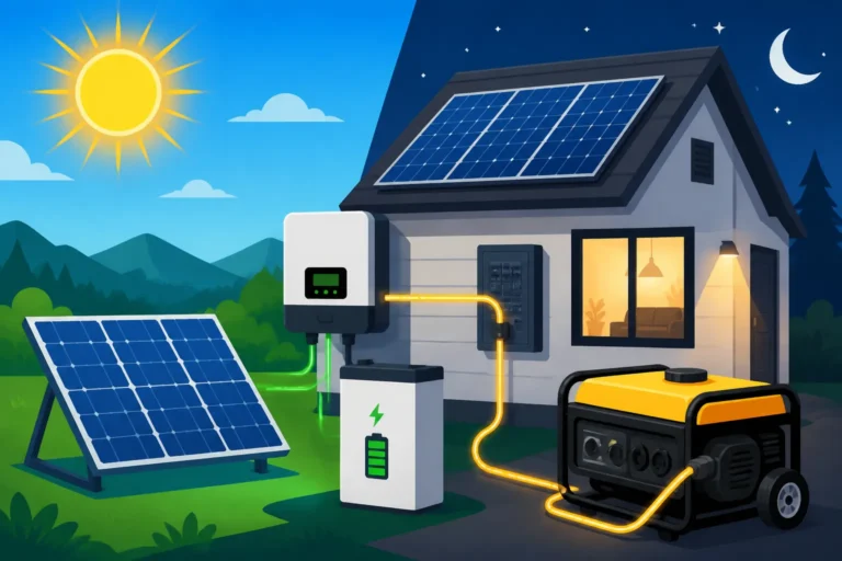
Crucially, you'll also find AC input terminals. This is where you connect an external AC power source. For many off-gridders, this means a portable or stationary generator, which fires up to supplement power during low solar production or high demand. For RV or tiny home dwellers, this might be a shore power connection from a campground pedestal. The inverter charger's internal transfer switch automatically detects when this AC input is present and, depending on your settings, can pass that power directly to your loads and/or use it to charge your batteries. This intelligent switching ensures you always have power, prioritizing the most efficient or available source.
In systems with a separate solar charge controller, that controller will connect directly to your battery bank, replenishing it with power from your solar panels. The inverter charger then draws from these charged batteries. However, as mentioned, some cutting-edge inverter chargers, like the Victron MultiPlus or Sol-Ark, integrate a high-efficiency MPPT (Maximum Power Point Tracking) solar charge controller right into the unit. This streamlines wiring and creates a truly integrated power management system. Understanding these various connections and how they're intended to interact is the first step towards a successful and safe installation. You'll find a detailed explanation of these connections in resources like how to connect batteries, inverter, and panels.
Essential Pre-Installation Steps
Alright, you've got your shiny new inverter charger, and you're eager to get it hooked up. Hold your horses for just a moment! Rushing this stage can lead to frustration, damaged equipment, or, worst of all, serious injury. Preparation is not just key; it's non-negotiable for a safe and effective off-grid installation.
Safety First: Disconnecting Power and Proper PPE
This isn't just a suggestion; it's the most critical part of any electrical work. Before you touch a single wire, ensure all potential power sources are completely disconnected and locked out. This means:
- Solar Panels: Cover your solar panels or disconnect them at a PV disconnect switch. Solar panels produce electricity even in dim light, and you absolutely do not want live DC current flowing while you're working.
- Battery Bank: Disconnect the negative terminal (and then the positive) of your battery bank. If you have a battery disconnect switch, open it. Batteries can deliver massive amounts of current, and a short circuit can cause fires, explosions, or severe burns.
- Generator/Shore Power: Unplug your generator or shore power cable. If it's a hardwired generator, ensure its breaker is off and locked.
- Grid Connection (if applicable): If your system is designed to interact with the grid in any way, ensure the main breaker to your property is OFF.
Once power is confirmed off, put on your Personal Protective Equipment (PPE). This should include:
- Insulated Gloves: Heavy-duty electrical gloves rated for the voltage you're working with.
- Eye Protection: Safety glasses or goggles to protect against sparks, splashes, or accidental contact.
- Non-Conductive Tools: Use tools with insulated handles. Avoid wearing jewelry, watches, or anything metallic that could act as a conductor.
- Appropriate Clothing: Wear long sleeves and pants made of natural fibers to minimize skin exposure and reduce the risk of synthetic materials melting onto your skin in case of an arc flash.
Working with high-voltage DC and AC systems carries inherent risks. Never assume a wire is dead. Always verify with a multimeter before touching it. You can learn more about general precautions in our guide on Off-Grid Solar Safety and Grounding.
Gathering Your Tools and Materials
Having the right tools for the job doesn't just make it easier; it makes it safer and ensures a professional-grade installation. Scrambling for a missing tool halfway through a critical connection is a recipe for mistakes.
Here's a breakdown of what you'll typically need:
- Multimeter: Essential for verifying voltages, continuity, and diagnosing issues.
- Wire Strippers and Crimpers: For precisely stripping insulation and securely crimping lugs onto cables. A good hydraulic crimper is invaluable for large gauge battery cables.
- Screwdrivers and Wrenches: Various sizes, often insulated, for tightening terminals and mounting hardware.
- Drill and Bits: For mounting the inverter charger and running conduit.
- Conduit Bender (if using rigid conduit): For clean cable runs.
- Cable Cutters: Heavy-duty cutters for thick battery cables.
- Heat Gun: For shrinking heat-shrink tubing over crimped connections.
Beyond tools, you'll need a range of materials:
- Proper Gauge Cables: This is paramount. The manual for your inverter charger will specify the required wire gauge for both DC (battery) and AC (input/output) connections. Using undersized wire is a fire hazard and leads to inefficient power transfer. You'll want to source high-quality components, and a quick search on Amazon can yield various options, but ensure they are rated for outdoor use if exposed.
- Fuses and Breakers: For overcurrent protection on both DC and AC circuits. These are life-savers in case of a fault.
- DC Disconnect Switches: For safe isolation of your battery bank and solar array.
- Bus Bars: For cleanly distributing DC power to multiple devices.
- Lugs: Copper or tinned copper lugs for connecting cables to terminals.
- Heat Shrink Tubing: For insulating crimped connections.
- Mounting Hardware: Bolts, screws, washers appropriate for your mounting surface.
- Conduit and Fittings: To protect your wiring, especially in exposed areas.
- Cable Ties/Clamps: For neat and secure cable management.
Before starting, double-check your inverter charger's manual for specific recommendations on cable sizing, fuse ratings, and any other unique material requirements. A well-stocked toolbox and meticulously gathered materials will save you immense time and prevent costly errors. Our guide on Off-Grid Solar Installation Tools Needed provides a more exhaustive list.
Locating and Mounting the Inverter Charger
Where you put your inverter charger isn't just a matter of convenience; it significantly impacts performance, safety, and longevity. Thoughtful placement is crucial.
Consider these factors when choosing a location:
- Proximity to Batteries: This is arguably the most critical factor for DC wiring. The cables connecting your inverter charger to your battery bank carry very high currents. Long runs of these heavy-gauge DC cables lead to voltage drop and energy loss, which means less power reaches your appliances and your system operates less efficiently. Keep these runs as short as physically possible – ideally less than 5 feet.
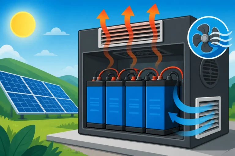
- Ventilation and Environment: Inverter chargers generate heat during operation. They need adequate airflow to dissipate this heat and prevent overheating, which can shorten their lifespan or trigger thermal shutdowns. Check your manual for minimum clearance requirements around the unit. Avoid enclosed spaces or areas prone to high temperatures. Also, protect the unit from direct sunlight, rain, dust, and excessive humidity. Many units are rated for indoor use only.
- Accessibility: While you won't be constantly adjusting it, you'll need access for initial configuration, occasional checks, and potential troubleshooting. Don't bury it behind permanent fixtures.
- Sturdy Mounting Surface: Inverter chargers, especially larger ones, can be quite heavy. Mount them securely to a solid surface like a wall stud, plywood backer board, or a robust metal frame. Always use appropriate fasteners that can bear the weight.
- Grounding Point: Ensure there's a good grounding point nearby for easy and safe connection of the inverter charger's chassis ground.
Once you've identified the ideal spot, carefully mark the mounting holes on your chosen surface using the inverter charger as a template. Drill pilot holes, and then securely fasten the unit to the wall or mounting rack. Ensure it's level and stable. Do not proceed with any wiring until the inverter charger is firmly in place. Proper mounting protects your investment and ensures safe operation.
Step-by-Step Wiring Guide
Now that the preparations are done, we can dive into the exciting part: making the electrical connections. This is where your off-grid dreams start to take physical form. Take your time, double-check every connection, and refer to your inverter charger's specific wiring diagram constantly.
Connecting to the Battery Bank
This is often the first and most critical electrical connection you'll make. Your battery bank is the heart of your off-grid storage, and a robust connection here is paramount for efficiency and safety.
First, identify the DC input terminals on your inverter charger. These are typically large, robust studs marked with "+" for positive and "-" for negative. Remember our earlier point about cable length: keep these battery cables as short as possible! They should also be the thickest cables in your system, as they carry the highest currents. The exact gauge will be specified in your inverter charger's manual, but for larger systems, you're often looking at 4/0 AWG or similar.
Before connecting to the inverter charger, ensure you have a properly sized DC disconnect switch and an appropriate fuse installed in the positive line as close to the battery bank as possible – ideally within 18 inches. This fuse is a critical safety device, protecting your cables and equipment from overcurrent in case of a short circuit. If your system runs on a 48V battery bank, ensure your fuse and disconnect are rated for 48V DC and the appropriate amperage.
Once your fuse and disconnect are in place (but open or off), prepare your battery cables. Strip the insulation to the length required for your chosen lugs. Crimp the lugs onto the cable ends securely. Many prefer hydraulic crimpers for large gauges to ensure a solid, low-resistance connection. After crimping, slide heat shrink tubing over the lug and cable junction and heat it until it's snug. This provides insulation and strain relief.
Connect the positive (+) cable from your battery bank (via the fuse and disconnect) to the positive terminal on the inverter charger. Then connect the negative (-) cable from your battery bank to the negative terminal on the inverter charger. Ensure all connections are clean, tight, and free of corrosion. Use a torque wrench if recommended by the manufacturer to ensure terminals are tightened to the correct specification. This prevents loose connections, which can lead to arcing, heat buildup, and system failures. For a deeper dive into optimal battery connections, check out our guide on How to Connect an Inverter to Batteries and How to Wire a Battery Bank.
| Component | Connection Point | Cable Type & Gauge (Example) | Safety Device Recommended |
|---|---|---|---|
| Battery Bank | Inverter Charger (DC Input) | DC (e.g., 4/0 AWG) | DC Disconnect, ANL/Class T Fuse |
| Solar Panels | Charge Controller (PV Input) | DC (e.g., 10 AWG) | PV Disconnect, DC Breaker |
| Charge Controller | Battery Bank (DC Input) | DC (e.g., 2 AWG) | DC Breaker |
| Generator/Grid | Inverter Charger (AC Input) | AC (e.g., 10 AWG) | AC Breaker |
| AC Loads | Inverter Charger (AC Output) | AC (e.g., 12 AWG) | AC Breaker Panel |
Wiring the Solar Charge Controller and Solar Array
The way your solar panels connect to your inverter charger depends on whether your inverter charger has a built-in solar charge controller or if you're using a separate, external unit.
Scenario 1: Inverter Charger with Integrated Solar Charge Controller
If your inverter charger boasts an integrated MPPT or PWM charge controller, your solar panels will connect directly to the inverter charger's dedicated PV input terminals. These terminals are usually clearly labeled "PV Input" or "Solar Input" and will have separate positive and negative connections.
Just like with your battery connections, follow strict safety protocols. Ensure your solar panels are covered or disconnected at a PV disconnect switch before wiring. You'll need properly sized DC wiring (e.g., 10 AWG or 12 AWG, depending on your array size and distance) running from your solar array. Install a PV disconnect switch and appropriate DC circuit breaker or fuse between your solar array and the inverter charger's PV input. This protects the wiring and allows for safe isolation of the array for maintenance. Connect the positive (+) solar array wire to the positive PV input terminal and the negative (-) solar array wire to the negative PV input terminal. Double-check polarity! Reversing it can cause serious damage.
Scenario 2: Separate Solar Charge Controller
If your inverter charger does not have an integrated solar charge controller, you'll need a standalone charge controller. In this setup, your solar panels connect to the PV input of the external charge controller, and the battery output of the charge controller connects directly to your battery bank. The inverter charger then draws its power from the same battery bank.
Again, ensure your solar panels are disconnected before beginning. Wire your solar array to the PV input terminals of your charge controller, installing a PV disconnect and overcurrent protection (DC breaker) in between. Then, wire the battery output terminals of your charge controller to your main battery bank, ensuring proper fusing (DC breaker) on this line as well. The charge controller manages the flow of power from your panels to your batteries, and the inverter charger then takes over from the battery side. For a more detailed look at these connections, our guides on How to Connect a Charge Controller and How to Wire an Off-Grid Solar System can be incredibly helpful.
Connecting AC Input (Generator/Shore Power) and AC Loads
These are the AC side connections, and they require adherence to AC electrical safety standards and codes. If you're unsure about any of these steps, it's always best to consult with a qualified electrician.
AC Input Connection (Generator/Shore Power)
Your inverter charger will have terminals designated for "AC Input" or "Generator/Grid Input." This is where you connect your external AC power source. This connection typically involves standard household wiring (e.g., 12 or 10 AWG Romex or individual conductors in conduit) from your generator's output or a shore power inlet.
You MUST include a properly sized AC circuit breaker in this line, usually located in a small subpanel or a dedicated breaker box near the input source. This breaker protects your wiring and the inverter charger from overcurrent. Connect the Hot (black), Neutral (white), and Ground (green or bare copper) wires from your AC input source to the corresponding terminals on the inverter charger. Ensure proper wire coloring and secure connections. The inverter charger's internal transfer switch will manage when this power is used to supply loads or charge batteries.
AC Output Connection (to Loads)
The "AC Output" terminals on your inverter charger are where the converted AC power flows to your appliances and devices. This is typically wired to a dedicated subpanel in your off-grid home, cabin, or RV.
From the AC output terminals of the inverter charger, run properly sized AC wiring to the main breaker of your off-grid distribution panel. This panel will then house individual circuit breakers for all your lights, outlets, and appliances. Again, use appropriate AC wiring (Hot, Neutral, Ground) and ensure all connections are tight and correctly polarized. You want to make sure your Off-Grid Solar Wiring Diagram Explained is meticulous for this section.
Grounding and Bonding
Proper grounding and bonding are absolutely crucial for safety. Your inverter charger will have a dedicated grounding lug or terminal. This must be connected with a thick, bare copper wire to your system's main grounding point – typically a ground rod driven into the earth for a stationary system, or the chassis/frame for an RV or mobile setup. All metal enclosures, conduit, and non-current-carrying metal parts of your system should also be bonded to this common ground. This provides a safe path for fault currents, protecting you from electrical shock. Never skip or cut corners on grounding! Our guide on Off-Grid Solar Safety and Grounding offers comprehensive details on this vital aspect.
Commissioning and Testing Your System
You've made all the connections, admired your neat wiring, and triple-checked everything. Now comes the moment of truth: bringing your off-grid inverter charger to life. This stage requires patience and methodical steps to ensure everything functions as intended and safely.
Initial Power-Up and Configuration
The sequence in which you power up your system is important and designed to protect your components. Always follow the manufacturer's recommendations, but a general sequence is:
- Batteries First: With all other disconnects open (solar, AC input, AC output), close your main DC disconnect switch from the battery bank to the inverter charger. You should hear the inverter charger power on, and its display or indicator lights should activate.
- Solar Second: If you have a separate charge controller, close the DC breaker from the charge controller to the batteries. Then, uncover your solar panels or close your PV disconnect. The charge controller should begin to register solar input and, if batteries need it, start charging. If your inverter charger has an integrated solar charge controller, you'd enable the PV input after the batteries are connected.
- AC Input (Generator/Shore Power) Third: If you have an external AC source, and you want to test it, connect your generator or shore power, then close the AC input breaker. The inverter charger should detect this input, potentially passing power to loads and initiating battery charging based on its settings.
- AC Output Last: Once you've confirmed the inverter charger is operational and stable, and all inputs are behaving as expected, you can then close the main AC breaker on your off-grid distribution panel, sending power to your loads.
After the initial power-up, you'll need to configure your inverter charger's settings. This is usually done through an onboard display, an external remote panel, or a dedicated app. For example, if you're installing a Renogy ONE system, its accompanying app makes configuration straightforward. Key settings to adjust include:
- Battery Type: Specify if you have LiFePO4, AGM, Flooded Lead-Acid, etc. This ensures the correct charging voltages and profiles are used.
- Charging Voltages: Set Absorption, Float, and Equalization voltages specific to your battery chemistry. Incorrect settings can severely damage batteries.
- Low Voltage Disconnect (LVD): Define the voltage at which the inverter shuts off to prevent over-discharging your batteries, protecting their lifespan.
- AC Input Limit: If using a generator or limited shore power, set the maximum AC current the inverter charger can draw to prevent overloading your source.
- Generator Auto-Start (if applicable): Configure parameters for when a generator should automatically start (e.g., low battery voltage, high load).
- Inverter Output: Confirm voltage (120V/240V) and frequency (60Hz/50Hz) match your regional standards and appliances.
Once configured, use your multimeter to verify voltages at various points: DC voltage at the battery terminals, DC voltage at the solar input (when connected), and AC voltage at the output terminals of the inverter charger. All readings should align with your expectations and the system's specifications.
Monitoring and Troubleshooting Common Issues
Even with the most careful installation, issues can sometimes pop up. The key is to approach troubleshooting systematically and understand what your inverter charger is trying to tell you.
Many modern inverter chargers feature a detailed display or an accompanying app that provides real-time data and error codes. This is your first line of defense in diagnosing problems. For example, if your Victron MultiPlus shows a specific error code, consulting the manual will tell you exactly what that means.
Common issues you might encounter and how to address them:
- No Power/Dead Display:
- Check battery connections: Are they tight? Is the DC disconnect closed?
- Verify battery voltage with a multimeter: Are the batteries completely dead?
- Check the DC fuse between the batteries and the inverter charger: Has it blown?
- No AC Output:
- Check if the inverter function is enabled.
- Look for overload warnings on the display: Are you trying to power too many appliances? Disconnect some loads and try again.
- Check for AC output breakers on the inverter charger itself or in your subpanel: Have they tripped?
- Is your battery bank below the LVD setting?
- Batteries Not Charging from Solar:
- Check solar panel connections at the charge controller (or inverter charger's PV input): Are they secure and correctly polarized?
- Verify solar panel voltage with a multimeter.
- Check PV disconnect and DC breakers for the solar array: Are they closed/on?
- Is the charge controller (or integrated function) set to the correct battery type?
- Batteries Not Charging from AC Input (Generator/Shore Power):
- Check AC input connection: Is the generator running, or is shore power connected and live?
- Check AC input breaker: Has it tripped?
- Verify AC input voltage with a multimeter.
- Ensure the AC input current limit isn't set too low, preventing effective charging.
Understanding Common Off-Grid Wiring Mistakes can also save you a lot of headache. Incorrect wire gauge, loose connections, reversed polarity, or improper fusing are frequent culprits behind system failures. Always start with the simplest checks and work your way through the system. A thorough Off-Grid Solar Installation Guide will often include a detailed troubleshooting section specific to the equipment. Don't be afraid to consult the manufacturer's manual or online forums for support.
Disclaimer
The information provided in this guide is for general educational purposes only and should not be considered professional electrical advice. Working with electricity, especially high-voltage DC and AC systems, carries inherent risks including serious injury or death. Always exercise extreme caution, disconnect all power sources before working, and wear appropriate personal protective equipment. If you are not comfortable or experienced with electrical installations, it is strongly recommended to consult with a qualified and licensed electrician. Local electrical codes and regulations may apply and must be followed. The author and publisher are not liable for any damages or injuries resulting from the use or misuse of this information.