Off-Grid Solar Wiring Diagram Explained
The world of off-grid solar can feel incredibly overwhelming, especially when you first lay eyes on a wiring diagram. It often looks like a spaghetti junction of lines, symbols, and numbers, leaving you wondering if you'll ever truly grasp how to connect everything safely and efficiently. If you've ever felt intimidated by the sheer complexity of bringing all those components together, you're not alone. This comprehensive guide is designed to demystify off-grid solar wiring diagrams, breaking down each essential component and connection so you can confidently plan, understand, and even troubleshoot your own independent power system.
Understanding the Foundation of an Off-Grid Solar System
Before we even begin to draw lines on paper or connect actual wires, it’s absolutely crucial to have a solid understanding of what an off-grid solar system is and how its main parts work together. Unlike grid-tied systems that send excess power back to the utility company, an off-grid setup is entirely self-sufficient, meaning it needs to generate, store, and distribute all its own power. This autonomy is incredibly appealing, but it also means every component has a critical role in maintaining a stable power supply, especially when the sun isn't shining.
What Makes an Off-Grid System Unique
The core difference with an off-grid system is its complete independence from the public utility grid. This isn't just about saving money on your electricity bill; it's about freedom, resilience, and often, enabling power in remote locations where extending power lines is astronomically expensive or even impossible. Imagine a cozy cabin nestled deep in the woods of upstate New York or a mobile workshop constantly on the move through the desert landscapes of Arizona. For these scenarios, relying on a central utility is simply not an option.
This independence places a huge emphasis on energy storage. While grid-tied systems can lean on the grid as a giant "battery," off-grid systems must capture and store every ounce of energy they produce. This reliance on stored energy, primarily in a battery bank, means careful planning and robust components are paramount. You're not just powering your devices; you're building a miniature power company for your specific needs, whether it's powering a single light bulb or an entire homestead.
The Basic Flow of Power
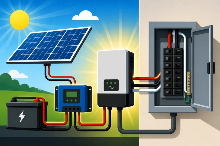
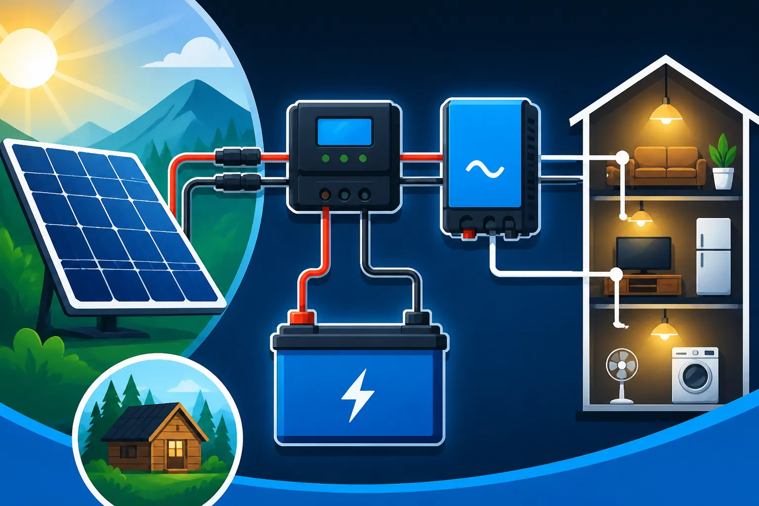
Think of your off-grid system as a river. The solar panels are the source, collecting sunlight and turning it into a powerful flow of DC (Direct Current) electricity. This raw power, however, is too erratic and strong to go straight into your delicate batteries or appliances. That's where the charge controller comes in, acting like a dam to regulate the flow, ensuring your batteries are charged safely and efficiently without overcharging or getting damaged.
Once the energy is stored in your battery bank – the reservoir of your system – it's ready to be used. Most modern homes and appliances run on AC (Alternating Current) power, so a crucial step is converting that stored DC power into usable AC power. This conversion is handled by the inverter, which is essentially the final gate that transforms the stored energy into the type of electricity your everyday devices can consume. Understanding this fundamental flow – panels to charge controller to batteries to inverter to loads – is the first step in making sense of any wiring diagram.
Essential Components in Any Off-Grid Wiring Diagram
Every off-grid solar wiring diagram, no matter how complex, will feature a few fundamental building blocks. Knowing what each component does and where it fits into the overall scheme is like learning the vocabulary before reading a book. If you understand the individual functions of these parts, the lines connecting them will start to make a lot more sense.
Solar Panels: The Energy Harvesters
Solar panels are the very beginning of your off-grid journey. They're the workhorses, absorbing photons from the sun and converting that light energy into DC electrical current. When you look at a wiring diagram, you'll see symbols representing individual panels or sometimes an entire array of panels. Each panel has a positive (+) and a negative (-) terminal, which are critical for proper connection.
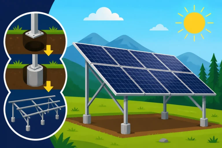
The panels are usually mounted in an area with maximum sun exposure, whether on a roof, a pole, or a ground mount. The amount of power they produce depends on their wattage, the intensity of the sunlight, and their orientation. In a diagram, you'll often see them grouped together, either in series or parallel, to achieve the desired voltage and current for the rest of your system. Understanding How Many Solar Panels for Off-Grid Living is often the first step in sizing your array.
Charge Controller: The Battery Guardian
Next in line is the charge controller, a device that acts as the protective intermediary between your solar panels and your battery bank. Its primary job is to regulate the voltage and current coming from the solar panels, ensuring that the batteries are charged correctly and preventing them from being overcharged or deep-discharged. Without a charge controller, you risk seriously damaging your expensive batteries, shortening their lifespan dramatically.
There are two main types of charge controllers you'll typically see in diagrams: Pulse Width Modulation (PWM) and Maximum Power Point Tracking (MPPT). MPPT controllers are generally more efficient, especially in larger systems or fluctuating weather conditions, as they can extract more power from the panels. A good wiring diagram will clearly show the connections from the solar array to the charge controller, and then from the charge controller to the battery bank, always noting the positive and negative terminals to maintain correct polarity. Many reputable brands like Renogy offer excellent charge controllers with clear installation instructions.
Battery Bank: The Power Reservoir
The battery bank is the heart of your off-grid system, providing power when your solar panels aren't generating electricity – at night, on cloudy days, or during peak demand. This is where all that hard-earned solar energy gets stored for later use. In a wiring diagram, you'll see symbols representing individual batteries connected together to form a larger bank.
The choice of battery chemistry (such as lead-acid or LiFePO4 lithium) significantly impacts your system's performance, lifespan, and, of course, the wiring requirements. Lithium batteries, like those from Battle Born or EG4, often come with integrated Battery Management Systems (BMS) that simplify some aspects of wiring and protection. Regardless of type, proper connection of your battery bank, including fuse placement and appropriate wire gauge, is absolutely critical for safety and efficiency. Understanding How Many Batteries for an Off-Grid System is a vital calculation that impacts your diagram.
Inverter: AC Power Converter
Finally, we come to the inverter. While your solar panels and batteries operate on DC power, most of your household appliances, tools, and electronics require AC power. The inverter's job is to convert the DC power stored in your battery bank into usable AC power for your home or cabin. This is often the largest and most complex component in terms of internal electronics.
Inverter ratings – in watts or kilowatts – indicate how much AC power it can supply at any given moment. Diagrams will show the inverter connecting directly to the battery bank (DC input) and then having AC output terminals that connect to your home's electrical panel or directly to AC loads. You'll also encounter terms like "pure sine wave" vs. "modified sine wave" inverters; pure sine wave is generally preferred for sensitive electronics and overall appliance health. A robust inverter is key to a functional off-grid system.
Demystifying the Solar Panel Array Wiring
The way you connect your solar panels together into an array is one of the most fundamental decisions you'll make, and it has a direct impact on the voltage and current that flows into your charge controller. A wiring diagram will show these connections clearly, often using symbols for panels and lines for wires, sometimes with arrows indicating current flow. It's not just about getting power; it's about getting the right kind of power for your specific charge controller and battery voltage.
Series Wiring for Higher Voltage
When you wire solar panels in series, you're essentially connecting the positive terminal of one panel to the negative terminal of the next panel, and so on. Think of it like a string of Christmas lights: if one goes out, the whole string might go out (though solar panels are more resilient!). In a series circuit, the voltage of each panel adds up, while the current (amperage) remains the same as that of a single panel.
For example, if you have four 12-volt solar panels, each producing 8 amps, wiring them in series would result in a 48-volt array that still produces 8 amps. This higher voltage is often desirable for larger systems or longer wire runs because it reduces current, which in turn minimizes voltage drop and allows for thinner, less expensive wiring from the array to the charge controller. It's critical that all panels in a series string are identical in terms of voltage and current output; otherwise, the weakest link will dictate the performance of the entire string. This is a common method for How to Wire Solar Panels in Series for higher system voltages.
Parallel Wiring for Higher Amperage
In contrast, parallel wiring connects all the positive terminals of your panels together, and all the negative terminals together. Imagine this as multiple pipes all feeding into a single, larger pipe – the water pressure (voltage) stays the same, but the volume of water (current) increases. When panels are wired in parallel, the voltage remains the same as that of a single panel, but the current (amperage) of each panel adds up.
So, if you take those same four 12-volt, 8-amp panels and wire them in parallel, you'll still have a 12-volt array, but it will now produce 32 amps (4 panels x 8 amps). Parallel wiring is often used for smaller 12V or 24V systems or when you need to maximize current for a shorter distance. It also offers a bit more redundancy; if one panel fails in a parallel array, the others will continue to produce power. However, higher amperage requires thicker wires to safely carry the increased current without overheating. This approach is thoroughly explained when considering How to Wire Solar Panels in Parallel.
Series-Parallel Combinations
For many medium to large off-grid solar systems, a combination of series and parallel wiring is the most effective approach. This allows you to achieve both a higher desired voltage and a higher total current, offering greater flexibility in system design. You might connect two panels in series to create a higher voltage string, and then connect several of these strings in parallel to increase the total current delivered to your charge controller.
A diagram showing a series-parallel configuration will look a bit more intricate, with multiple "strings" of series-connected panels, and then these strings themselves being connected in parallel at a combiner box. This method is excellent for balancing wire sizing, system efficiency, and panel count, especially when dealing with higher voltage battery banks like 24V or 48V. Always ensure you have appropriate overcurrent protection, such as fuses or circuit breakers, within your combiner box where these strings are brought together, protecting each string from potential faults.
Connecting Your Charge Controller to Batteries
This stage of the wiring diagram is absolutely critical, as it bridges the power generation part of your system with the energy storage heart. The connection between the charge controller and the battery bank must be robust, properly sized, and correctly fused to ensure both safety and the longevity of your expensive batteries. Getting this wrong can lead to serious issues, from damaged equipment to fire hazards.
Direct Current (DC) Connections
When you look at the wiring diagram for this section, you'll see clearly marked positive (+) and negative (-) terminals on both the charge controller and the battery bank. It is paramount to connect positive to positive and negative to negative, ensuring correct polarity. Reversing polarity can instantly damage your charge controller, and in some cases, your batteries. Most modern charge controllers have built-in reverse polarity protection, but it's always best practice to double-check every connection before making it live.
The wires connecting the charge controller to the battery bank carry the full charging current, so they must be appropriately sized to handle this load without overheating. Undersized wires can lead to significant voltage drop, reducing charging efficiency, and can even become a fire hazard. Consult wire gauge charts and consider the distance between your components. The shorter the distance and thicker the wire, the better. Many reputable brands like Victron Energy provide detailed wiring diagrams and recommendations for optimal wire sizing with their charge controllers.
Fuse and Breaker Placement
Safety is non-negotiable in any electrical system, and the connections between your charge controller and batteries are no exception. A crucial element in your wiring diagram will be the placement of fuses or circuit breakers. These devices are designed to protect your components and prevent fires in the event of a short circuit or overcurrent situation.
The general rule of thumb is to place a fuse or circuit breaker on the positive line as close as possible to the battery bank. This ensures that the entire circuit, including the charge controller, is protected. The sizing of this fuse or breaker should be appropriate for the maximum current that the charge controller can output and the capacity of your wiring. For example, if your charge controller has a maximum output of 60 amps, you might use an 80-amp fuse, ensuring it's slightly larger than the maximum expected continuous current but smaller than the wire's maximum rating. For more details on protecting your system, refer to guides like How to Install Fuses and Breakers.
Battery Bank Configuration
Your battery bank itself will have internal wiring, connecting individual batteries in series, parallel, or a combination of both to achieve the desired system voltage (e.g., 12V, 24V, 48V) and capacity. A detailed wiring diagram will show these internal connections. For example, if you have four 12V batteries and want a 48V system, you'd wire them all in series. If you want a 12V system with more capacity, you'd wire them in parallel.
When connecting multiple batteries, ensure all cables are of the same length to promote even charging and discharging, which helps extend the lifespan of your battery bank. Also, connecting batteries with a battery monitor, often involving a shunt, is a smart addition to any system. This allows you to accurately track your battery's state of charge, voltage, and current flow, giving you crucial insights into your system's health. For comprehensive details, checking out How to Wire a Battery Bank can be incredibly helpful.
Integrating the Inverter: AC Power for Your Appliances
The inverter is where your stored DC battery power transforms into the AC electricity that runs most of your daily life. This component is typically connected directly to your battery bank, and then its output feeds into your AC load center or directly to appliances. Understanding these connections in a wiring diagram is vital for safely powering your home or vehicle.
Inverter to Battery Bank Connections
Just like the charge controller, the inverter's DC input terminals (positive and negative) must be connected directly and correctly to your battery bank. These connections are often the most robust in your entire system because the inverter can draw very high currents from the batteries, especially when powering large AC loads or starting motors (surge power). You'll usually see very thick battery cables in your diagram here, indicating the need for heavy-gauge wiring to minimize voltage drop and prevent overheating.
Again, fuses or circuit breakers are absolutely essential on the positive DC line between the battery bank and the inverter. This fuse needs to be sized appropriately for the inverter's maximum continuous DC current draw and its surge capacity. Undersized fuses will constantly blow, while oversized fuses won't offer adequate protection. Always consult your inverter's manual for specific fuse recommendations. Brands like Sol-Ark and Outback Power are known for their high-quality inverters that require careful, robust wiring.
AC Output and Load Center Integration
Once the inverter converts DC power to AC power, that electricity needs a pathway to your appliances. A wiring diagram will show the AC output from the inverter connecting to an AC distribution panel (also known as a breaker panel or load center). This panel is where individual circuits for your lights, outlets, refrigerator, and other appliances are managed, each protected by its own circuit breaker.
For smaller systems, you might see the inverter's AC output directly feeding into a few dedicated outlets. For larger homes or cabins, the inverter will often feed into a main breaker panel, sometimes referred to as a subpanel, allowing it to power multiple circuits throughout the structure. It’s crucial that your AC wiring adheres to local electrical codes and uses appropriate wire gauges and circuit breakers for each load. Understanding How to Install an Off-Grid Inverter is a key step in this process.
Understanding Inverter Types
Not all inverters are created equal, and your wiring diagram might reflect different capabilities. Pure sine wave inverters produce a clean, stable AC waveform that's identical to or even better than grid power. These are ideal for sensitive electronics, medical equipment (like CPAP machines), and anything with a motor. Modified sine wave inverters, while cheaper, produce a "stepped" waveform that can be problematic for some devices and generally less efficient.
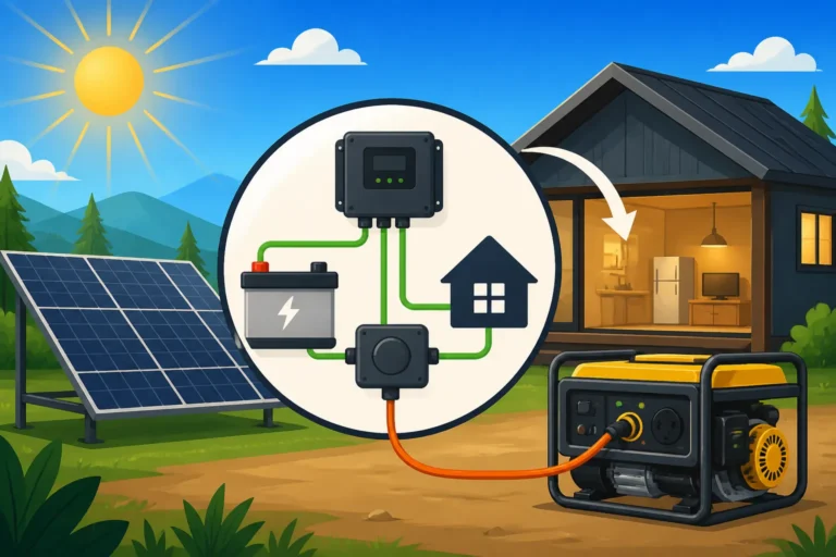
Some advanced inverters are also inverter/chargers, meaning they can not only convert DC to AC but also charge your batteries from an external AC source, like a backup generator. If your diagram shows a connection from an AC input (e.g., generator) to your inverter, you're likely dealing with an inverter/charger or a hybrid inverter, which adds another layer of complexity and capability to your system. Properly sizing your inverter is critical; explore What Size Inverter to Run A Refrigerator or What Size Inverter to Run An Air Conditioner for specific examples.
Safety First: Grounding and Protection in Your Diagram
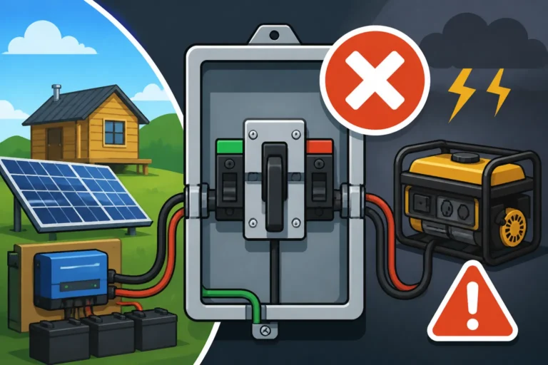
Safety isn't just a recommendation in off-grid solar; it's an absolute requirement. A well-designed wiring diagram prioritizes safety by incorporating proper grounding, overcurrent protection, and disconnect switches. These elements are designed to protect both your equipment and, more importantly, you from electrical hazards. Never cut corners on safety components; they are a small investment compared to the potential consequences of an electrical fault.
System Grounding Explained
Grounding (or earthing, as it's called in some regions) is arguably the most critical safety feature in any electrical system. It provides a safe path for electrical current to flow into the earth in the event of a fault, preventing dangerous voltage buildup that could cause electric shock or equipment damage. In your off-grid wiring diagram, you'll see a dedicated grounding wire, typically green or bare copper, connecting various metal components to a ground rod driven deep into the earth.
Every major metal component in your system – the solar panel frames, the mounting racks, the inverter chassis, the charge controller casing, and your electrical subpanel – must be bonded together and connected to a common ground point. This creates an equipotential bonding network. The main grounding electrode conductor then connects this network to a grounding rod (or rods). Local electrical codes, such as the National Electrical Code (NEC) in the United States, provide specific guidelines for proper grounding, which must be followed meticulously. Learning How to Ground an Off-Grid Solar System is a crucial skill.
Fuses and Circuit Breakers: Overcurrent Protection
We've touched on these already, but it bears repeating: fuses and circuit breakers are your system's primary defense against overcurrents and short circuits. A fuse contains a small wire that melts and breaks the circuit when too much current flows through it. A circuit breaker automatically trips, disconnecting the circuit, and can be reset once the fault is cleared. Your wiring diagram will show these strategically placed throughout the system.
You should find fuses or breakers on the positive line:
- Between the solar array and the charge controller (PV disconnect).
- Between the charge controller and the battery bank.
- Between the battery bank and the inverter.
- For each individual AC circuit coming off your inverter's output.
The goal is to protect each segment of the circuit and the components connected to it. The amperage rating of each fuse or breaker must be carefully matched to the maximum current of the circuit it protects and the current carrying capacity of the wire. This is a topic thoroughly covered in guides like How to Install Fuses and Breakers.
Disconnect Switches: For Maintenance and Emergencies
Beyond continuous protection, your wiring diagram should also include manual disconnect switches. These switches allow you to completely isolate different parts of your system for maintenance, repairs, or in case of an emergency (like a fire). Having easily accessible disconnects is not just good practice; it's often a legal requirement.
Key disconnect points usually include:
- A DC disconnect between the solar array and the charge controller (often part of a combiner box). This allows you to safely shut down power from the panels.
- A DC disconnect between the battery bank and the inverter. This is crucial for working on the inverter or battery bank.
- An AC disconnect on the output of the inverter, especially if it's feeding into a main electrical panel.
These switches ensure that you or an electrician can safely work on specific components without fear of electrical shock from other parts of the live system. Always ensure these switches are clearly labeled and rated for the voltage and current of the circuit they are interrupting.
Reading and Interpreting Different Off-Grid Solar Wiring Diagrams
Staring at a wiring diagram can feel like looking at a foreign language if you don't know the symbols or conventions. But once you understand the basic elements and how they're typically laid out, these diagrams become incredibly valuable tools for planning, installing, and troubleshooting your off-grid solar system. It's about recognizing patterns and understanding the story the lines and shapes are trying to tell you.
Common Symbols and Their Meanings
Every wiring diagram uses standardized symbols to represent different components. Once you learn these, you can identify what's what, regardless of the manufacturer or specific setup. Here's a quick rundown of some common symbols you'll encounter:
| Component | Common Symbol | Description |
|---|---|---|
| Solar Panel (PV Module) | A square with a diagonal arrow pointing out. Sometimes multiple squares connected. | Converts sunlight into DC electricity. |
| Battery | A series of parallel lines, usually two long and two short. | Stores electrical energy (DC). Often shown in a bank configuration. |
| Charge Controller | A rectangle with "CC" or specific circuit symbols inside. | Regulates charging from solar panels to batteries. |
| Inverter | A rectangle with a sine wave or "INV" inside, often with DC input/AC output. | Converts DC battery power to AC power for appliances. |
| Fuse | A small rectangle with a squiggle line inside, or an "S" shape. | Overcurrent protection device that melts to break a circuit. |
| Circuit Breaker | A rectangle with a line that can pivot, sometimes with a "trip" indicator. | Reusable overcurrent protection device. |
| Disconnect Switch | A break in a line with a diagonal line across, sometimes a box with "SW". | Manual switch to isolate a circuit. |
| Ground | Three decreasing parallel lines, or a triangle. | Connection to the earth for safety. |
| DC Loads | A circle with an "X" or "DC" inside (for light), or generic box. | Devices that run directly on DC power (e.g., 12V lights, USB chargers). |
| AC Loads/Panel | A rectangle with "AC" or "LP" (load panel) inside. | Devices or entire electrical panel running on AC power. |
Understanding these basic symbols is the first step to unlocking any diagram's secrets. You might find a more detailed legend on some diagrams, especially from manufacturers like Renogy or Victron, that clarifies their specific notations.
Tracing the Power Flow
Once you know the symbols, the next step is to trace the power flow. Start at the beginning, with the solar panels, and follow the lines. Remember the basic path:
- Solar Panels (PV Array): Generate DC power.
- PV Disconnect/Combiner Box (Optional but Recommended): Fuses/breakers for panel strings.
- Charge Controller: Regulates DC power to the batteries.
- Battery Bank: Stores DC power.
- Battery Disconnect: Manual switch.
- Inverter: Converts DC to AC power.
- Inverter AC Disconnect: Manual switch.
- AC Load Center/Breaker Panel: Distributes AC power to your appliances.
Look for arrows on the lines, which indicate the direction of current flow. Pay close attention to positive and negative lines, often color-coded (red for positive, black for negative for DC; various colors for AC depending on region). Note where fuses, breakers, and disconnects are placed. This sequential tracing helps you understand the system's operational logic.
Manufacturer-Specific Diagrams and General Schematics
You'll encounter two main types of diagrams: general schematics and manufacturer-specific ones. General schematics offer a high-level overview, showing typical connections without getting into the nitty-gritty of specific models. These are great for understanding overall system architecture.
Manufacturer-specific diagrams, on the other hand, are provided by brands like EcoFlow, Bluetti, or Renogy for their particular kits or components. These diagrams are invaluable because they show the exact terminals, recommended wire sizes, and specific safety devices for their equipment. Always refer to the manufacturer's diagram when installing their products. If you buy a solar kit from Amazon, for instance, it should come with a detailed wiring guide specific to its components. These diagrams are your blueprint for a successful and safe installation, so take the time to study them thoroughly.
Common Wiring Mistakes to Avoid and How to Troubleshoot
Even seasoned off-gridders can make mistakes, especially when dealing with complex electrical systems. Being aware of the most common wiring errors and knowing how to troubleshoot them can save you a lot of headache, expense, and potential danger. A well-understood wiring diagram is your best friend in both avoiding and fixing these issues.
Polarity Reversal
This is one of the most common and potentially damaging mistakes, especially when connecting panels to the charge controller or the charge controller to the batteries. Reversing the positive and negative connections (connecting positive to negative and vice-versa) can instantly damage sensitive electronics like charge controllers and inverters. While many modern devices have reverse polarity protection, it's not foolproof.
How to Avoid: Always double-check your connections using a multimeter before making them live. Trace your wires carefully, especially when working with long runs or multiple components. Red for positive, black for negative is a common convention for DC wiring – stick to it rigorously.
Troubleshooting: If your system isn't working after installation and you suspect polarity reversal, immediately disconnect all power. Visually inspect all connections. If a component is smoking or smells burnt, it's likely damaged. Use your multimeter to confirm polarity at each connection point.
Undersized Wiring and Inadequate Fusing
Using wires that are too thin for the amount of current they carry is a recipe for disaster. Undersized wires heat up, leading to energy loss, reduced system performance, and a serious fire risk. Similarly, using fuses or breakers with incorrect ratings (too low, leading to constant trips; too high, leading to no protection) leaves your system vulnerable.
How to Avoid: Always calculate your maximum current draw for each segment of your system and consult a wire gauge chart to select the appropriate gauge. Account for voltage drop over longer distances. For fusing, always follow the manufacturer's recommendations for each component and ensure the fuse rating is appropriate for the wire size. Remember, the fuse protects the wire, not necessarily the device. You can find excellent resources on How to Size Wire and Cables and How to Size Fuses and Breakers.
Troubleshooting: If wires are hot to the touch or circuit breakers are constantly tripping, you likely have undersized wiring or an overloaded circuit. Measure the current flow with a clamp meter and compare it to your wire and fuse ratings. Replace undersized wires with appropriate gauges and correctly size your fuses or breakers.
Improper Grounding
An improperly grounded system is a dangerous system. Missing ground connections or poor ground electrode installation can leave your system susceptible to electrical shocks and damage from lightning strikes or fault conditions.
How to Avoid: Ensure every metal component (panel frames, racks, inverter chassis, etc.) is properly bonded and connected to a common grounding point. Use the correct gauge grounding wire and install a ground rod (or multiple rods, depending on code) correctly. Always follow local electrical codes for grounding. Refer to a comprehensive guide like Off-Grid Solar Safety and Grounding for detailed steps.
Troubleshooting: If you experience shocks when touching metal components, or if sensitive electronics are failing without clear cause, it could be a grounding issue. Inspect all ground connections for tightness and corrosion. Test the resistance of your ground electrode system if you have the proper equipment.
Loose Connections
It sounds simple, but loose connections are a very common cause of system failures, intermittent power, and even hotspots that can lead to fires. Vibrations, temperature changes, and improper installation can all cause connections to loosen over time.
How to Avoid: Always ensure all terminal screws are tightened securely to the manufacturer's specifications. Use appropriate tools (e.g., torque wrenches for specific battery terminals). For outdoor connections, use weatherproof connectors like MC4s and ensure they are properly crimped and sealed. Periodically inspect your connections for tightness, especially after the system has been running for a while.
Troubleshooting: Intermittent power, flickering lights, or components that suddenly stop working can all point to loose connections. Visually inspect every connection point, gently wiggling wires to see if they're secure. Use an infrared thermometer to check for hot spots on terminals, which can indicate high resistance due to a loose connection.
By paying meticulous attention to your off-grid solar wiring diagram, understanding each component's role, and committing to best safety practices, you can build a reliable, efficient, and safe power system. The initial complexity is just a puzzle waiting to be solved, and with this knowledge, you're well on your way to off-grid independence.
Disclaimer
The information provided in this guide is for general informational purposes only and does not constitute professional electrical advice. Working with electricity can be dangerous. Always consult with a qualified electrician or solar professional and adhere to all local electrical codes and regulations before installing or modifying any electrical system. Incorrect installation can result in serious injury, death, or property damage.