How to Wire a 24V Off-Grid System
Stepping into the world of off-grid solar can feel a bit like learning a new language, especially when it comes to the nitty-gritty of wiring. Many folks, perhaps accustomed to smaller 12V systems in their RVs or simple setups, find themselves scratching their heads when they decide to scale up to a 24V system for a cabin, tiny home, or a more robust mobile setup. The thought of connecting all those components – panels, batteries, charge controllers, and inverters – can be genuinely intimidating, making you worry about everything from blowing a fuse to outright damaging expensive equipment. But don't you worry! This comprehensive guide is designed to walk you through the process of how to wire a 24V off-grid system, providing clear, actionable steps to ensure your setup is both safe and efficient.
Understanding the Basics of a 24V System
Before we dive headfirst into connecting wires, it's really helpful to understand why you're choosing a 24V system and what makes it tick. It’s not just an arbitrary number; there are real advantages and specific components that differentiate it from its 12V or 48V siblings.
Why Choose 24V Over 12V or 48V
When you’re planning your off-grid power setup, one of the first big decisions you’ll face is choosing your system voltage. While 12V systems are super common for smaller applications like campers, basic van builds, or really simple shed lighting, they start to show their limitations pretty quickly once your power demands grow. Imagine you're trying to power a small cabin with a mini-fridge, a few lights, and perhaps a water pump. If you stick with 12V, you’ll find yourself needing incredibly thick, expensive wires to carry the higher current without excessive voltage drop. This is where 24V really shines.
A 24V system effectively halves the current for the same amount of power compared to a 12V system. Less current means you can use thinner, more affordable wiring for the same distance and power output, which is a huge benefit both for your wallet and for ease of installation. It’s a fantastic middle-ground, offering better efficiency and scalability than 12V without the sometimes higher upfront cost and complexity of a full 48V setup. For instance, a small family upgrading their RV's solar system might realize their existing 12V setup is struggling to keep up with a newly installed small mini-fridge and a couple of extra LED strip lights. They'd find that stepping up to 24V would allow them to run these new appliances more efficiently and with less stress on their wiring, often without needing to completely re-wire their entire rig with much thicker cables. While 48V systems are ideal for large homes with heavy loads like air conditioners and washing machines, 24V hits that sweet spot for moderate power needs, striking a great balance between performance and practicality.
Key Components of a 24V Off-Grid System
Every off-grid solar system, regardless of voltage, relies on a core set of components working in harmony. For a 24V system, the crucial part is ensuring all these components are rated for 24V operation where appropriate. Mismatched voltages are a surefire way to run into problems or, at worst, damage your equipment.
Here’s a rundown of what you’ll need:
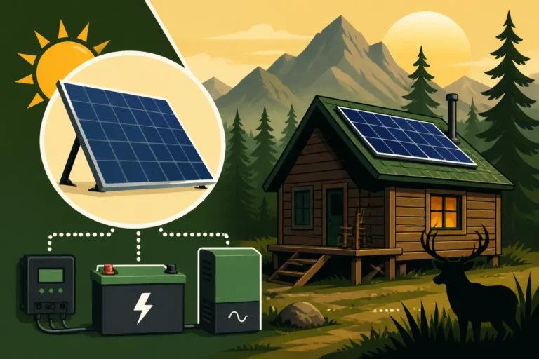
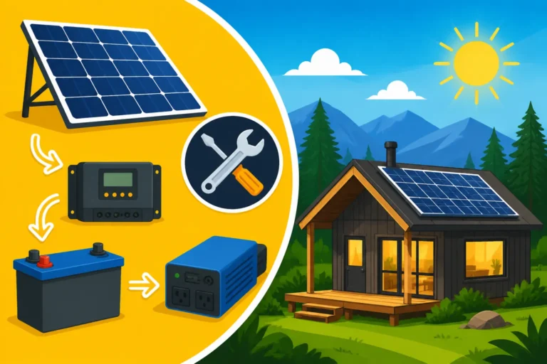
- Solar Panels: These are your power generators, converting sunlight into DC electricity. While individual panels are often rated at a nominal 12V, you’ll connect them in series (or series-parallel) to achieve your desired 24V system voltage.
- Charge Controller: This intelligent device manages the power flow from your solar panels to your batteries. It protects your batteries from overcharging and over-discharging, which is absolutely vital for their lifespan. For 24V systems, an MPPT (Maximum Power Point Tracking) charge controller is almost always recommended over a PWM (Pulse Width Modulation) controller because it’s significantly more efficient, especially with higher panel voltages. It can take a higher voltage input from your panels and efficiently convert it down to the 24V needed for your battery bank, maximizing your energy harvest.
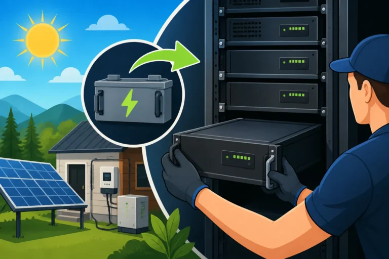
- Battery Bank: This is your energy storage. For a 24V system, your battery bank must be configured to output 24V. This usually means wiring two 12V batteries in series, or for larger capacity, wiring multiple 24V strings in parallel. We’ll delve deeper into this configuration shortly.
- Inverter: Your inverter is the bridge between your DC battery power and your AC appliances. Most household electronics run on AC (alternating current), so the inverter converts the 24V DC from your batteries into 120V or 240V AC. It’s crucial that your inverter is designed to accept a 24V DC input.
- Fusing, Breakers, and Disconnects: These are your essential safety components. Fuses and circuit breakers protect your wiring and equipment from overcurrents and short circuits, preventing electrical fires and component damage. DC disconnects allow you to safely isolate parts of your system for maintenance or in an emergency. Never, ever skimp on safety components.
- Wiring and Connectors: Proper wire gauge, quality connectors (like MC4 connectors for your solar panels), and robust terminals are paramount for a safe and efficient system. Don't underestimate the impact of undersized or poorly connected wiring on your system's performance and safety.
Choosing the right components from reputable brands like Renogy or Victron can significantly impact the longevity and reliability of your system. Many components, especially charge controllers and inverters, will clearly state their compatible system voltage, so always double-check those specifications before making a purchase.
Step-by-Step Wiring Your 24V Solar Panels
Now that you understand the core components, let’s get into the exciting part: wiring up those solar panels to give you the 24V power you need. This section will cover how to configure your panels and connect them safely to your charge controller.
Connecting Solar Panels for 24V Output
The way you connect your solar panels determines the total voltage and amperage they produce. To achieve 24V from standard 12V nominal solar panels, you primarily use series wiring. Remember, when you wire panels in series, their voltages add up, but their current (amps) remains the same. When you wire them in parallel, their currents add up, but their voltage remains the same.
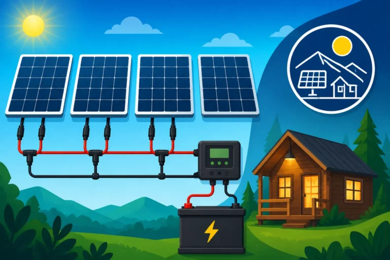
- Series Connection: If you have individual 12V nominal solar panels (e.g., a common 100-watt panel with a ~18V-20V Vmp, or 'voltage at maximum power'), you'll need to connect two of them in series to get a nominal 24V output. To do this, connect the positive (+) terminal of the first panel to the negative (-) terminal of the second panel. The remaining negative terminal of the first panel and the positive terminal of the second panel become your main outputs for that 24V series string. For example, two 100W 12V panels, each putting out 5 amps, when wired in series, will give you approximately 40V (20V + 20V) at 5 amps. This higher voltage is excellent for an MPPT charge controller.
- Series-Parallel Connection: What if you have four 12V panels and need more current (and thus more total wattage) at 24V? You would create two separate 24V series strings (as described above) and then connect these two strings in parallel. So, you'd have one pair of panels wired in series, and another pair wired in series. Then, you'd connect the positive output of the first series string to the positive output of the second series string. Do the same for the negative outputs. This way, the voltage stays at 24V nominal (or ~40V actual operating voltage from the panels), but the current doubles. So, two 24V series strings each producing 5 amps would, when paralleled, produce 10 amps at 24V nominal (or ~40V).
Consider a cabin owner with four 100W 12V panels. To get a robust 24V system, they would wire two of these 100W panels in series to create a 200W, ~40V string. They would then repeat this for the other two panels, creating a second identical 200W, ~40V string. Finally, they would connect these two 40V strings in parallel, yielding a total of 400W at ~40V, which is then fed into their 24V MPPT charge controller. If you're looking for more details on these methods, check out our guide on How to Wire Solar Panels in Series and How to Wire Solar Panels in Parallel.
Wiring Panels to the Charge Controller
Once your panels are configured for the desired voltage, the next step is to connect them to your charge controller. This is a critical connection, and order matters!
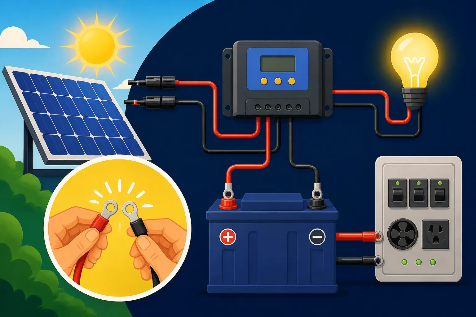
Important Rule: Always connect your batteries to the charge controller first, before connecting your solar panels. This allows the charge controller to sense the battery voltage and properly initialize, preventing potential damage to the controller or batteries.
Here’s how to do it:
- Safety First: Before touching any wires, ensure your solar panels are covered or disconnected to prevent any live voltage. Always work with the system de-energized.
- DC Disconnect and Fusing: It’s highly recommended to install a DC-rated breaker or fuse box between your solar panels and your charge controller. This serves as a critical safety measure, allowing you to easily disconnect the panels from the system for maintenance or in an emergency, and protecting against overcurrents.
- Cable Sizing: Select the appropriate wire gauge for your solar panel array. This depends on the total current your panels will produce and the distance between your panels and your charge controller. Undersized wires lead to voltage drop and wasted energy. You can find many online calculators to help you determine the correct wire gauge. As a rule of thumb, bigger is generally safer. Consult our guide on How to Size Wire and Cables for more in-depth information.
- Connect Positives: Run a positive (+) cable from the combined positive output of your solar array (or from your DC combiner box) to the "PV+" or "Solar+" terminal on your 24V charge controller.
- Connect Negatives: Run a negative (-) cable from the combined negative output of your solar array to the "PV-" or "Solar-" terminal on your 24V charge controller.
- Secure Connections: Ensure all connections are tight and secure. Use appropriate MC4 connectors for all panel connections to ensure weather resistance and a solid electrical link.
Once the batteries are connected to the charge controller and the charge controller is ready, you can then uncover your panels or flip on your DC disconnect. The charge controller should then begin to register the input from your panels and start charging your battery bank.
Building and Connecting Your 24V Battery Bank
Your battery bank is the heart of your off-grid system, storing the energy harvested by your solar panels. For a 24V system, correctly configuring and connecting your batteries is paramount for safety and performance.
Configuring Batteries for 24V
This is often where new off-gridders can get a little tripped up, especially if they're used to 12V setups. To create a 24V battery bank, you'll need to wire 12V batteries in series. If you're working with true 24V batteries, then it's simpler – you might just connect them in parallel to increase capacity.
Let's break down how to get to 24V:
- Using 12V Batteries: The most common approach for a 24V system is to use two 12V batteries wired in series. To do this, you connect the positive (+) terminal of the first 12V battery to the negative (-) terminal of the second 12V battery. The remaining negative terminal of the first battery and the positive terminal of the second battery then become the main negative and positive terminals for your entire 24V battery bank. For example, if you have two 100Ah 12V LiFePO4 batteries (like those readily available on Amazon), wiring them in series gives you a 24V 100Ah bank.
- Increasing Capacity with Parallel Strings: If you need more capacity (more amp-hours) at 24V, you would create multiple 24V series strings and then connect those strings in parallel. So, imagine you want a 24V 200Ah bank using 100Ah 12V batteries. You'd set up two separate 24V series strings (each with two 12V batteries in series). Then, you'd connect the main positive terminal of the first 24V string to the main positive terminal of the second 24V string. Do the same for the negative terminals. This gives you a 24V system with double the amp-hour capacity.
- Using True 24V Batteries: Some manufacturers, like EG4, offer dedicated 24V LiFePO4 batteries. If you're using these, you would simply connect multiple 24V batteries in parallel to increase your total amp-hour capacity while maintaining the 24V system voltage. This is often simpler as it reduces the number of series connections.
When wiring batteries, especially lead-acid types, ensure they are of the same age, capacity, and type to prevent imbalances. For LiFePO4 batteries, a good Battery Management System (BMS) will handle balancing, but it’s still best practice to start with matched batteries. Need more guidance on these connections? Our article on How to Wire a Battery Bank has even more detail.
Here's a quick look at common battery configurations for a 24V system:
| Battery Type (Nominal) | Quantity | Wiring Configuration | Resulting Bank Voltage | Resulting Bank Capacity (Ah) |
|---|---|---|---|---|
| 12V 100Ah | 2 | 2 in Series | 24V | 100Ah |
| 12V 100Ah | 4 | 2x (2 in Series) in Parallel | 24V | 200Ah |
| 12V 200Ah | 2 | 2 in Series | 24V | 200Ah |
| 24V 100Ah | 1 | N/A | 24V | 100Ah |
| 24V 100Ah | 2 | 2 in Parallel | 24V | 200Ah |
Connecting the Battery Bank to the Charge Controller and Inverter
Once your 24V battery bank is assembled, it's time to connect it to the rest of your system. This is another critical step where the correct sequence and safety measures are crucial.
-
Battery to Charge Controller Connection:
- As mentioned before, this is the first electrical connection you make in your off-grid system.
- Install a large DC-rated fuse or circuit breaker close to your battery bank's positive terminal. This is your main battery fuse and is absolutely essential to protect your entire system from catastrophic short circuits.
- Run a heavy gauge positive (+) cable from the positive side of your main battery fuse (which is connected to your battery bank's positive terminal) to the "Battery+" terminal on your 24V charge controller.
- Run a heavy gauge negative (-) cable from your battery bank's negative terminal to the "Battery-" terminal on your 24V charge controller.
- Ensure all connections are robust and tight.
- Once connected, your charge controller should power up and display the battery voltage.
-
Battery to Inverter Connection:
- Your inverter draws significant power, so its connection to the battery bank must be direct and well-protected.
- Install another appropriately sized DC-rated fuse or circuit breaker close to your battery bank's positive terminal for the inverter. This fuse should be rated for the maximum continuous current draw of your inverter.
- Run a very heavy gauge positive (+) cable from the positive side of the inverter's fuse (which is connected to your battery bank's positive terminal) to the positive (+) DC input terminal on your 24V inverter.
- Run an equally heavy gauge negative (-) cable from your battery bank's negative terminal to the negative (-) DC input terminal on your 24V inverter.
- Pro Tip: For large systems, busbars can be incredibly useful. A busbar is a metallic strip or bar that distributes current from the battery bank to multiple components (like your charge controller and inverter) while keeping your wiring neat and organized. This also simplifies the connection of additional loads if your charge controller has a limited output capacity.
- For a comprehensive walkthrough on connecting these components, take a look at our Off-Grid Solar Installation Guide.
Remember, the gauge of the wires used for your battery and inverter connections is extremely important. These carry the highest currents in your system, and undersized wires can lead to dangerous overheating and significant power loss. Always refer to your inverter and battery specifications for recommended wire sizes.
Integrating the Inverter and Loads
With your solar panels charging your 24V battery bank, the next crucial step is getting that stored energy to your appliances. This involves your inverter, which transforms DC power into usable AC power, and directly connecting any DC loads.
Wiring the 24V Inverter for AC Power
The inverter is the workhorse that allows you to run standard household appliances, tools, and electronics that operate on alternating current (AC). Without it, you'd be limited to 24V DC devices.
- DC Input Connection (Review): We briefly covered this, but it's worth reiterating. The DC input terminals of your 24V inverter must be connected directly to your 24V battery bank, using very thick gauge wires and protected by a high-amperage DC fuse or circuit breaker positioned as close to the battery bank as possible. This ensures that the inverter has a stable and robust power supply and that the DC circuit is protected. For instance, a 3000W 24V inverter can draw well over 100 amps at full load, so you're looking at very thick cables, often 2/0 or 4/0 AWG, depending on the length of the run. Check out How to Connect an Inverter to Batteries for more specific details.
- AC Output Wiring: This is where your inverter becomes a mini power utility.
- Dedicated Outlets: For smaller setups, some inverters come with standard AC outlets built-in. You can simply plug your appliances directly into these.
- AC Breaker Panel: For larger cabins or homes, you’ll want to wire the inverter's AC output to a small AC breaker panel. This panel functions much like a miniature version of a traditional home electrical panel. The inverter's AC output connects to the main input of this panel, and then individual circuit breakers within the panel distribute power to different circuits (e.g., lights, outlets, refrigerator) throughout your off-grid dwelling. This provides centralized control and critical overcurrent protection for each AC circuit.
- Transfer Switch (Optional but Recommended): If you plan to incorporate a backup generator, installing an automatic transfer switch (ATS) after your inverter’s AC output is a smart move. This device seamlessly switches your AC loads from inverter power to generator power if the battery voltage gets too low, or vice versa, ensuring continuous power without manual intervention.
It's important to use a pure sine wave inverter for any sensitive electronics like laptops, televisions, or medical devices. Modified sine wave inverters are cheaper but can cause humming, reduced efficiency, or even damage to some appliances.
Connecting DC and AC Loads
Your off-grid setup will likely have a mix of DC and AC appliances. Knowing how to connect each efficiently is key to maximizing your power usage.
- Direct DC Loads: Some appliances are designed to run directly on DC power, such as many LED lights, USB charging ports, and sometimes specialized 24V fridges or fans.
- These can be connected directly to your battery bank via a dedicated DC fuse panel. This fuse panel allows you to protect each individual DC load with its own fuse, preventing a single faulty appliance from affecting your entire system.
- Many charge controllers also have "Load" terminals. For smaller DC loads, you can connect them here. The advantage is that the charge controller can manage these loads, often providing low-voltage disconnect to protect your batteries from being fully drained by DC appliances. However, these load terminals usually have a limited current capacity, so they are not suitable for heavy DC loads.
- A homesteader might run their cabin's primary LED lighting and a small DC-powered water pump directly from a DC fuse panel connected to their 24V battery bank, ensuring these essential items have robust and protected power.
- AC Loads: These are the appliances that require the inverter's output. Think of common household items like microwaves, coffee makers, larger refrigerators, washing machines, or power tools.
- As discussed, these connect either directly to the inverter's outlets or, more commonly for permanent installations, to an AC breaker panel that is fed by the inverter's output.
- Each circuit in the AC panel should be protected by its own appropriately sized AC circuit breaker.
- For example, a dedicated circuit might run to your kitchen outlets for a microwave or toaster, while another supplies power to your well pump if it's an AC model.
- Effectively managing both types of loads is crucial for an efficient system. You can learn more about managing these connections in our guide on How to Wire AC and DC Loads.
Safety and Best Practices in 24V Wiring
Wiring an off-grid solar system involves significant electrical currents, and safety should always be your absolute top priority. Skipping safety measures can lead to equipment damage, fire, or serious injury.
Fusing, Breakers, and Disconnects
These components are your system's guardians, designed to interrupt current flow when something goes wrong. Never, ever, build an off-grid system without them.
- Battery Bank Fusing: This is perhaps the most critical fuse in your entire system. A large, DC-rated fuse (often a Class T or ANL fuse) must be installed on the positive cable leaving your battery bank, as close to the battery terminal as possible. This fuse protects your entire system from a short circuit within the main DC wiring or inverter. Its rating should match the maximum continuous current your inverter can draw, plus a small buffer.
- PV Array Fusing/Breakers: As previously discussed, an appropriately sized DC circuit breaker or fuse should be placed between your solar panel array and your charge controller. This protects the wiring from your panels to the controller and allows you to safely disconnect the panels. If you have multiple series strings of panels, it's often best practice to fuse each string individually using a combiner box before they merge.
- Charge Controller to Battery Fusing: While often integrated into an all-in-one unit, it's good practice to have a fuse or breaker between the charge controller and the battery, especially if the controller is not protecting against back-currents.
- Inverter DC Input Fusing: Your inverter's main DC input must be protected by a large DC-rated fuse or breaker, as close to the battery bank as possible. This protects the inverter and its associated wiring from overcurrents.
- AC Breakers: If you're wiring your inverter to an AC breaker panel, each individual AC circuit (e.g., for lights, outlets, appliances) must have its own AC-rated circuit breaker. This protects the AC wiring and connected appliances from overloads.
- Disconnect Switches: Install manual DC disconnect switches for your solar array and battery bank. These allow you to completely and safely cut off power to various parts of your system for maintenance, repairs, or in emergency situations. Brands like Renogy often include these safety components in their larger kits, making it easier for DIYers to ensure they have the necessary protections.
Always ensure that all fuses, circuit breakers, and disconnect switches are DC-rated for DC circuits and AC-rated for AC circuits. Using AC components on DC circuits or vice versa can be extremely dangerous.
Proper Grounding and Cable Management
Beyond fuses and breakers, proper grounding and meticulous cable management are essential for a safe, reliable, and efficient 24V off-grid system.
- Grounding: Electrical grounding is not just a suggestion; it's a critical safety feature. All metallic components of your solar system that could potentially become energized (like the frames of your solar panels, metal racking, the chassis of your inverter, and the enclosure of your charge controller) must be properly grounded to an earth ground rod. This provides a safe path for fault currents to dissipate, protecting people from electrical shock and helping to prevent damage to equipment from lightning strikes. The National Electrical Code (NEC) provides specific guidelines for grounding, even for off-grid systems. For a detailed explanation, refer to our article on How to Ground an Off-Grid Solar System.
- Cable Sizing and Type: As we've stressed, correctly sizing your wires is paramount. Too thin, and you risk overheating, voltage drop, and fire. Use high-quality, UV-resistant, appropriately insulated copper wiring. For DC outdoor runs, typically use specific solar PV wire (e.g., PV Wire or USE-2), which is designed for direct burial or exposed outdoor use. For indoor DC wiring, choose flexible stranded wire suitable for the current and environment.
- Cable Management and Protection:
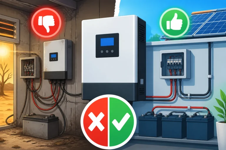
- Neatness Counts: Organize your wiring with zip ties, cable clamps, and wire loom. A neat system is easier to troubleshoot, looks professional, and reduces the risk of chafing or accidental damage.
- Conduit: Protect exposed wiring (especially outdoors or in areas where it might be mechanically damaged) by running it through electrical conduit. This shields cables from UV degradation, animals, and physical impacts.
- Strain Relief: Ensure cables entering enclosures or terminals have proper strain relief to prevent tugging on the connection points.
- Waterproofing: For any roof penetrations (like where solar cables enter your cabin or RV), use appropriate sealing methods to prevent water leaks.
You can find high-quality wiring, fuses, and connectors from reputable suppliers online, often on platforms like Amazon, but always prioritize quality and proper ratings for your specific system voltage and current. Investing a little extra in good quality wiring and safety components is always worth it in the long run.
Common Challenges and Troubleshooting
Even with the best planning and execution, off-grid solar systems can sometimes present challenges. Knowing what to look for and how to troubleshoot common issues can save you a lot of headache and keep your power flowing.
Voltage Drop and Inefficient Power
Voltage drop is a silent killer of efficiency in any DC electrical system, and a 24V off-grid setup is no exception. It occurs when your wires are too long or too thin for the amount of current they are carrying. The resistance in the wire literally "drops" some of your voltage along the way, meaning less power reaches your components or batteries.
- The Problem: Imagine your solar panels are trying to send 40 volts to your charge controller, but due to long, undersized wires, only 38 volts are actually making it. That 2-volt drop represents wasted energy, meaning your batteries take longer to charge, and your overall system isn't performing at its peak. This can be even more pronounced between your battery bank and your inverter, where very high currents are involved. An inverter demanding 100 amps from your 24V battery bank needs robust cables; if the voltage at the inverter drops too low due to poor wiring, the inverter might fault out, shutting down your AC power.
- Mitigation Strategies:
- Thicker Wires: This is the simplest and most effective solution. The thicker the wire (lower AWG number), the less resistance it has, and thus less voltage drop.
- Shorter Runs: Keep your cable runs as short as practically possible. Every foot adds resistance.
- Online Calculators: Use reliable online voltage drop calculators. You input your system voltage, current, wire length, and wire gauge, and it will tell you the expected voltage drop. Aim for a voltage drop of no more than 2-3% for your main power runs.
- Higher System Voltage (Future Proofing): If you anticipate significant future expansion and worry about wire sizes becoming unmanageable, consider designing an expandable system that could eventually move to 48V. As we discussed, higher voltage systems naturally reduce current, making voltage drop less of an issue for the same power.
- Troubleshooting: If your system feels sluggish or your components aren't getting the expected power, grab a multimeter. Measure the voltage at different points: directly at your solar panels, at the input to your charge controller, at your battery terminals, and at the DC input to your inverter. Significant discrepancies (more than a volt or two for low voltage systems, or 2-3% for higher voltage runs) indicate a voltage drop issue. Our article on How to Prevent Voltage Drop in Off-Grid Wiring offers even more strategies.
Battery Imbalance and System Failures
Your battery bank is a critical component, and ensuring its health is paramount. Battery imbalance, especially in series-connected banks, can lead to reduced capacity, premature battery degradation, and even system failures.
- Battery Imbalance Explained: When you connect multiple batteries in series, they ideally should charge and discharge equally. However, subtle differences in internal resistance, age, or manufacturing tolerances can cause one battery to charge or discharge faster than others. Over time, this leads to an imbalance where one battery might be consistently overcharged or over-discharged while others are not, leading to its early demise and reducing the effective capacity of your entire bank.
- Why It Matters: In a 24V bank made of two 12V batteries in series, if one 12V battery drops to 10V while the other is still at 12V (for a total of 22V), that 10V battery is being severely over-discharged, which is extremely detrimental, especially for lead-acid batteries.
- Solutions and Best Practices:
- Matched Batteries: Always start with batteries of the same brand, model, age, and capacity, especially when wiring in series.
- Battery Management System (BMS): For LiFePO4 batteries, a good quality BMS is non-negotiable. Most LiFePO4 batteries come with an integrated BMS that actively monitors cell voltages and balances them during charging, protecting against overcharge, over-discharge, overcurrent, and extreme temperatures. This is a huge advantage over lead-acid batteries.
- Equalization (for Lead-Acid): Some lead-acid batteries require periodic "equalization" charges, which is a controlled overcharge to help balance cell voltages. Check your battery manufacturer's recommendations.
- Monitoring: Install a reliable battery monitor (shunt-based is best) to accurately track your state of charge, voltage, current, and health of your battery bank. This allows you to catch issues early.
- General Troubleshooting:
- Check All Connections: Loose connections are a frequent culprit for intermittent power, unexpected shutdowns, and heat buildup. Periodically inspect and tighten all terminals.
- Fuses and Breakers: Always check your fuses and reset breakers first if a component or circuit isn't working. A blown fuse is a sign of an underlying issue, not just a nuisance.
- Component Settings: Ensure your charge controller and inverter settings (e.g., battery type, charge voltages, low voltage disconnects) are correctly programmed for your specific 24V battery chemistry and capacity. Incorrect settings can severely harm your batteries.
- Multimeter Use: A multimeter is your best friend for diagnosing electrical issues. Use it to check voltages, continuity, and current (with a DC clamp meter).
- If you encounter persistent issues, our comprehensive guide on How to Troubleshoot Off-Grid Solar can provide a more in-depth look at diagnostics.
Disclaimer
The information provided in this guide is for general informational and educational purposes only. While we strive to offer accurate and helpful advice, off-grid solar installation involves working with electricity, which can be dangerous if not handled properly. Always prioritize safety, consult local electrical codes, and if you are unsure about any aspect of your installation, seek assistance from a qualified and licensed electrician or solar professional. Improper installation can lead to equipment damage, fire, or serious injury. We are not liable for any damages or injuries resulting from the use or misuse of this information.