How to Ground an Off-Grid Solar System
If you're diving into the world of off-grid living, you've probably spent countless hours researching solar panels, batteries, and inverters. But there's one crucial, often overlooked, and sometimes downright intimidating aspect that can make or break your system's safety and longevity: grounding. It’s the unsung hero that protects your valuable equipment and, more importantly, you from electrical hazards. This comprehensive guide is here to demystify the process, walking you through everything you need to know about properly grounding your off-grid solar system so you can enjoy peace of mind and reliable power.
Why Grounding Your Off-Grid Solar System is Non-Negotiable
It’s easy to think of grounding as just another step on a long checklist, a technicality that electricians fuss over. But for an off-grid solar system, proper grounding isn't just about following rules; it's fundamental to safety and functionality. Imagine a sudden lightning strike or a fault within your system – without proper grounding, the consequences can range from catastrophic equipment damage to severe injury or even death. It’s the invisible shield that directs dangerous electrical currents safely away.
Protecting Your Equipment from Electrical Surges
Your off-grid solar system is an investment, often a significant one. Solar panels, charge controllers, inverters, and battery banks are all sensitive electronic components. Electrical surges, whether from lightning or an internal fault like a short circuit, can send thousands of volts through your system in an instant, utterly destroying everything in its path. Without a low-resistance path to the earth, this surge has nowhere to go but through your expensive gear. Think of it like a pressure relief valve; grounding gives that excess energy a safe escape route.
For instance, consider a scenario where lightning strikes near your solar array. The electrical charge induced in the panels and wiring can quickly overwhelm the system's components if there's no path for it to dissipate into the ground. A properly grounded system, however, will shunt that dangerous energy directly into the earth, minimizing damage to your inverter, batteries, and other critical parts. This protection extends beyond dramatic events; even minor faults or static electricity can degrade components over time if not properly handled by a robust grounding system. It’s a foundational layer of defense that keeps your power flowing and your wallet happy.
Ensuring Personal Safety in Your Off-Grid Setup
This is perhaps the most critical reason for proper grounding: protecting human life. Electricity and water are a dangerous combination, and even dry conditions can present electrocution hazards if something goes wrong. If there's an electrical fault, like a wire chafing and touching a metal enclosure, that metal component can become energized. Without a ground path, touching that enclosure would complete a circuit through your body, leading to a potentially fatal shock. The thought alone is enough to send shivers down any DIY enthusiast's spine.
Imagine you're out in your remote cabin, adjusting some wiring, and unknowingly touch a metal conduit that has become energized due to an internal fault. If the system isn't properly grounded, that conduit could be at full system voltage, and you become the quickest path to ground. A properly grounded system, on the other hand, provides a much lower resistance path for that fault current, tripping a breaker or blowing a fuse almost instantaneously and safely de-energizing the fault before you even have a chance to complete the circuit. This is why every metal part of your system that could potentially become energized needs to be connected to earth. It ensures that any fault current immediately finds the easiest path back to the source, activating protective devices and keeping you safe.
Meeting Electrical Codes and Insurance Requirements
While off-grid setups often operate outside the direct jurisdiction of utility companies, they are by no means exempt from electrical safety standards. In many areas, especially if you plan to ever sell your property or tie into any kind of grid in the future, adhering to national and local electrical codes, like the National Electrical Code (NEC) in the United States, is essential. These codes exist for a reason: to ensure public safety. Even for completely isolated systems, the principles outlined in the NEC for grounding are best practices you should follow. Ignoring these can lead to fines, difficulties with inspections, or even legal repercussions if an incident occurs.
Furthermore, if you have any type of insurance for your off-grid property or dwelling, be it homeowner's or liability insurance, proper electrical grounding is almost certainly a prerequisite. Insurers typically require systems to be installed according to recognized safety standards. If a fire or electrical injury occurs and it's found that your solar system was improperly grounded, your insurance claim could be denied, leaving you on the hook for massive damages and medical bills. Following established guidelines, even for a "DIY" system, demonstrates due diligence and helps protect your financial well-being. Always check your local building and electrical codes, as some remote counties might have specific requirements, and consider consulting with a local electrician familiar with off-grid installations, especially regarding Off-Grid Solar Permit Requirements.
Understanding the Basics of Electrical Grounding
Before we dive into the nitty-gritty of installation, let's clear up some common misconceptions and establish a solid understanding of what grounding actually is in the context of your off-grid solar system. It’s not just sticking a rod in the ground; it's a carefully designed system to manage electrical faults and surges.
What is Grounding and How Does it Work?
At its core, grounding means connecting a circuit or electrical equipment to the earth. The earth acts as a massive, stable electrical reference point, providing an infinite sink for excess electrical energy. When a fault occurs, like a live wire touching a metal casing, the ground wire provides a low-resistance pathway for the fault current to flow directly into the earth. This sudden rush of current activates overcurrent protection devices, such as circuit breakers or fuses, which then shut off the power to the faulty circuit, preventing further danger.
Without this ground path, the fault current has no easy route. The voltage builds up on the faulty equipment, making it a shock hazard. When you complete the circuit by touching it, you become the path to ground, which is exactly what we want to avoid. The principle relies on Ohm's Law (V=IR), where current (I) will always follow the path of least resistance. By creating an extremely low-resistance path to the earth via a ground wire and ground rod, you ensure that fault currents prefer this path over, say, your body. This concept is fundamental to Off-Grid Solar Wiring Best Practices and overall system reliability.
The Difference Between Equipment Grounding and System Grounding
It's easy to conflate these two terms, but understanding the distinction is crucial for proper off-grid solar design.
Equipment Grounding (EG): This refers to connecting all non-current-carrying metal parts of your electrical system to the grounding electrode conductor. This includes solar panel frames, mounting racks, inverter casings, charge controller enclosures, battery boxes, and any metal conduit or junction boxes. The purpose of equipment grounding is purely safety-related: to prevent these metal parts from becoming energized due to a fault (e.g., insulation breakdown, loose wire). If a live wire accidentally touches a grounded metal casing, the fault current flows to ground, tripping a breaker and making the system safe.
System Grounding (SG) or Utility Grounding: This involves connecting one of the current-carrying conductors of your electrical system (typically the neutral wire in AC systems or the negative terminal in DC systems, or sometimes a specific grounding terminal within your inverter) to the earth. For off-grid systems, this connection is usually made at the main distribution panel or the inverter/charger unit. The purpose of system grounding is to stabilize the voltage to ground, provide a reference point for circuit operation, and offer a path for lightning and other high-voltage surges to dissipate. While it doesn't directly protect against shock from faulty equipment (that's equipment grounding's job), it provides an overall system reference and protection against external transient overvoltages. In some off-grid inverters like those from Victron or Sol-Ark, the chassis ground terminal might be separate from the DC negative, and both need careful attention.
Key Components of an Off-Grid Grounding System
A robust grounding system is made up of several interconnected parts, each playing a vital role. Knowing these components will help you understand How to Wire an Off-Grid Solar System safely.
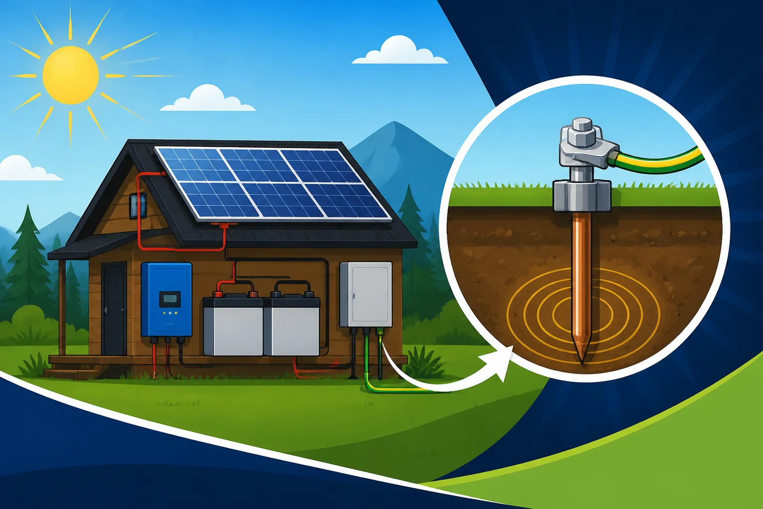
- Ground Rods/Electrodes: These are typically copper-clad steel rods, usually 8 feet (2.4 meters) long and at least 5/8 inch (1.6 cm) in diameter, driven vertically into the earth. They provide the primary connection to the "ground." In some cases, multiple rods are used, spaced at least 6 feet apart, to achieve lower resistance to earth. Other types of electrodes can include metal water pipes, building steel, or even concrete-encased electrodes (Ufer grounds).
- Grounding Electrode Conductor (GEC): This is the main wire connecting your system's primary grounding point (e.g., your main electrical panel or inverter's grounding busbar) to your ground rod(s). It needs to be sized correctly based on the system's overcurrent protection and potential fault currents.
- Equipment Grounding Conductors (EGCs): These wires connect all the individual metal components (panel frames, inverter chassis, charge controller chassis, metal conduits) back to a common grounding busbar, which is then connected to the GEC. These are crucial for the safety aspect discussed earlier.
- Bonding Jumpers: Short lengths of wire or specialized straps used to ensure electrical continuity between metal parts that might not otherwise be reliably connected, such as between sections of a solar panel mounting rail.
- Grounding Lugs and Clamps: Specialized connectors used to attach grounding wires securely to ground rods, panel frames, and other metal components. For instance, Renogy often includes grounding lugs with their larger solar kits, which is a good indication of the importance of these components. These need to be corrosion-resistant and rated for direct burial if used underground.
- Surge Protective Devices (SPDs): While not strictly grounding components, SPDs work in conjunction with grounding to shunt transient overvoltages (like lightning strikes) safely to the earth. They are typically installed on both the DC side (between panels and charge controller) and the AC side (at the inverter output or main panel).
All these components work together to create a cohesive and protective system. Neglecting any one part can compromise the integrity of the entire grounding scheme.
Step-by-Step Guide to Grounding Your Solar Panels
Your solar panels are the most exposed part of your system, constantly subjected to the elements, making their proper grounding absolutely critical. This isn't just about the panels themselves, but the entire metallic structure that supports them.
Grounding Panel Frames and Racking
Every single solar panel has an aluminum frame. This frame, along with the metal racking system that holds the panels, needs to be connected to earth ground. Why? Because if there's a fault within a panel, or if lightning strikes the array, these metal frames can become energized, posing a shock hazard to anyone who touches them. This is where equipment grounding comes into play.
Start by ensuring good electrical continuity between all individual panel frames and the racking system. Many modern racking systems, especially reputable brands like IronRidge or EcoFasten, come with built-in bonding capabilities, often using integrated hardware that pierces through anodization to create a connection. If your racking doesn't have this, or if you're using a DIY setup, you'll need to use dedicated How to Mount Off-Grid Solar Panels grounding clips or lugs that attach to each panel frame and connect them to the metal rails. From the rails, a continuous equipment grounding conductor (typically bare copper or green insulated wire) runs back to a central grounding point, often a busbar in a combiner box or directly to your main grounding electrode conductor. Don't rely on the mounting bolts alone for grounding; always use proper grounding hardware designed for this purpose.
Connecting the PV Array to the Main Grounding System
Once your individual panels and racking are bonded together, you need to connect this entire array to your main grounding system. This connection is typically made using a dedicated equipment grounding conductor that runs from the solar array's grounding busbar (often found in a PV combiner box) down to your inverter's grounding busbar or your main electrical panel's ground bus. This wire provides the low-resistance path for any fault currents originating in the array to safely travel to earth.
The size of this grounding conductor is critical and determined by the size of your DC overcurrent protection device (e.g., the breaker protecting your solar array). Generally, a #6 AWG bare copper wire is a common size for many residential-scale off-grid systems, but it's crucial to consult the NEC (Article 690 for solar PV systems and Article 250 for grounding and bonding) or a qualified electrician to ensure proper sizing based on your specific system's amperage. This wire should be protected from physical damage, often run in conduit, and terminated securely with appropriate lugs and clamps. Remember, a chain is only as strong as its weakest link, and an undersized or poorly connected grounding wire won't offer the protection you need.
Considerations for Different Mounting Types
The method of mounting your panels can influence how you approach grounding, but the core principles remain the same.
- Roof Mounts: For panels mounted on a residential roof, the grounding conductor from the array needs to safely enter the building and connect to the main service panel's ground bus or the inverter's ground bus. Ensure all roof penetrations for wires are properly sealed to prevent leaks. The metal racking itself should be bonded to the building's existing grounding system if applicable, or have its own dedicated path to the main ground rod. How to Install Roof-Mounted Solar Panels covers how to integrate these elements structurally and electrically.
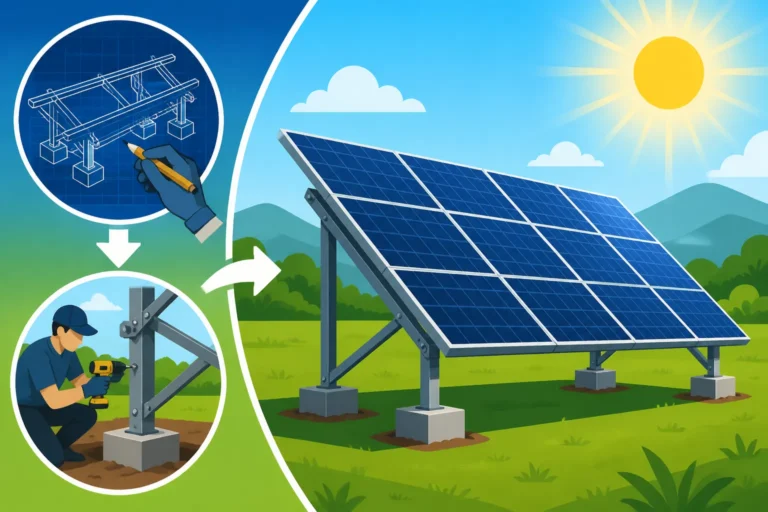
- Ground Mounts: Ground-mounted arrays often have the advantage of being closer to the ground, potentially simplifying the run for the grounding electrode conductor to the ground rods. However, these systems might require their own dedicated ground rods in addition to the main system ground, especially if they are far from the main dwelling. Ensure the metal framework of the ground mount is fully bonded and connected to the main grounding system. Building a How to Build and Install a Ground Mount correctly includes its grounding.
- RV, Van, or Boat Mounts: Mobile off-grid setups have unique challenges. While you can't exactly drive an 8-foot ground rod into the earth every time you park, the principles of equipment grounding still apply. All metal frames, vehicle chassis, and appliance enclosures must be bonded together. This creates an equipotential bonding plane. When the vehicle is stationary, a temporary ground rod or connection to a shore power ground (if available) can provide additional safety. For stationary mobile setups, connecting to a permanent ground rod is recommended. For example, a Renogy RV kit would typically instruct you to bond the panel frames to the vehicle's chassis, which acts as the main ground plane for the mobile system.
Regardless of the mounting type, the goal is always to create a low-resistance path from any potential fault point to the earth, or at least to an equipotential bonding plane for mobile applications.
Grounding Your Charge Controller, Inverter, and Battery Bank
These are the heart of your off-grid solar system, managing power flow and storing energy. Improper grounding here is a recipe for disaster, potentially affecting both DC and AC sides of your electrical setup. It's crucial to follow manufacturer instructions precisely for these components, as grounding specifics can vary. If you're unsure about How to Connect Batteries, Inverter, and Panels, grounding is a fundamental prerequisite.
Properly Grounding Your Charge Controller
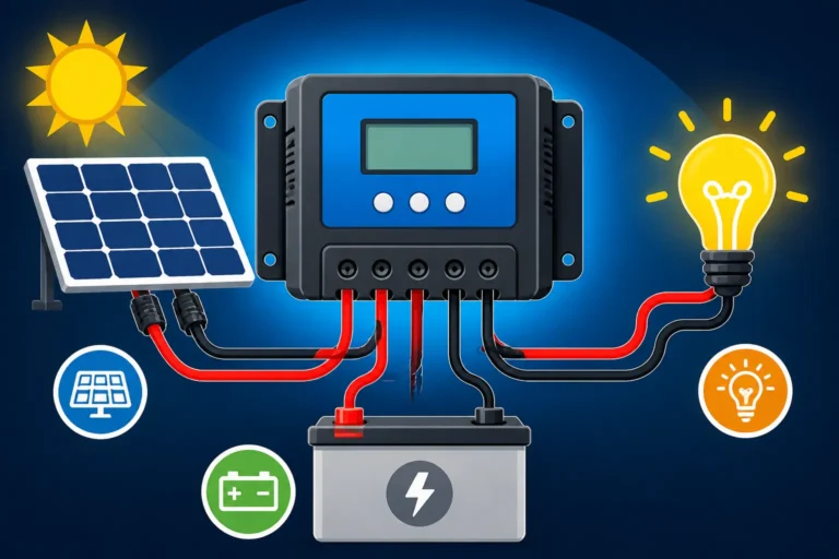
Your charge controller is the bridge between your solar panels and your battery bank. Most charge controllers, particularly MPPT models from brands like Victron or EPEVER, will have a dedicated ground lug or terminal on their chassis. This terminal needs to be connected via an equipment grounding conductor back to your system's main grounding busbar. This ensures that if there's an internal fault, or if the metal casing of the charge controller becomes energized, the fault current has a safe path to ground, tripping the appropriate DC breaker.
It’s important that this ground wire is sized correctly, often correlating with the input/output wiring size of the controller. For example, if your solar input wires are 8 AWG, your ground wire should typically be at least 8 AWG. Always refer to the charge controller's manual for specific grounding requirements. Some larger, more sophisticated charge controllers may also have an integrated surge protection device (SPD) connection point, which should also be tied into your main grounding system to protect against lightning and other transients from the solar array.
Essential Inverter Grounding Procedures
The inverter is arguably the most critical component to ground correctly, especially if it's producing AC power for your home or cabin. Most inverters will have a distinct ground lug on their exterior chassis. This is where you'll connect an equipment grounding conductor. For many modern inverter-chargers, like the Growatt or EG4 all-in-one units, this chassis ground needs to be connected to your main grounding electrode conductor (GEC) or the main ground busbar in your electrical panel.
Additionally, if your inverter has a built-in AC transfer switch and is capable of passing through shore power or generator power, its neutral-to-ground bond must be handled very carefully. In a typical off-grid system, the neutral conductor from the inverter's AC output should be bonded to the inverter's chassis ground only when the inverter is operating in island mode (not connected to an external AC source). Many advanced inverters allow you to configure this bond internally. If you have an external AC distribution panel, the neutral-to-ground bond should occur only once at the first means of disconnect. Improper neutral-to-ground bonding can create dangerous ground loops or prevent GFCI/AFCI devices from functioning correctly. Always follow the manufacturer's instructions for your specific inverter model, as well as local electrical codes, to ensure correct neutral and ground connections. This area is where many DIYers make critical errors, so consulting Off-Grid Solar Installation Guide or a professional is highly recommended.
Securely Grounding Your Battery Bank
While batteries themselves don't typically have ground lugs in the same way panels or inverters do, the metal trays, racks, or enclosures holding them must be grounded. For lead-acid batteries, the negative terminal is often bonded to the system's common ground. For LiFePO4 (lithium iron phosphate) batteries, it’s even more critical to ensure that any metal housing or rack is connected to the equipment ground. This prevents those metal parts from becoming energized if there’s a fault or an accidental short.
Furthermore, it's good practice to install a battery monitor with a shunt (like those offered by Victron Energy) that is also properly integrated into your system's grounding scheme. The shunt's metal housing, if present, should also be bonded to the equipment ground. When you're dealing with substantial amounts of stored energy, as found in a battery bank, any fault can release tremendous amounts of power. A robust grounding system ensures that this energy has a safe path away, protecting both the batteries and anyone working nearby. How to Wire a Battery Bank safely involves understanding these grounding principles from the start.
Selecting the Right Grounding Components and Materials
Choosing the right materials for your grounding system is just as important as the installation process itself. Substandard components can corrode, fail, or simply not provide the low-resistance path needed for effective grounding, rendering your entire safety system useless. This is where you might find yourself browsing for specific components on platforms like Amazon or specialized solar suppliers.
Choosing Appropriate Ground Rods and Electrodes
The most common and effective grounding electrode is the copper-clad steel ground rod. These typically measure 8 feet in length and 5/8 inch or 3/4 inch in diameter. Copper cladding provides excellent conductivity and corrosion resistance, while the steel core gives it strength for driving into the earth. The goal is to drive the rod fully into undisturbed soil to achieve a low resistance to ground, ideally 25 ohms or less. If a single rod doesn't meet this resistance, you may need to install additional rods, spaced at least 6 feet apart, and bond them together with a grounding conductor.
In some situations, other electrodes can be used:
- Metal Underground Water Pipe: If you have a continuous metal underground water pipe (at least 10 feet in the earth) entering your building, it can serve as a grounding electrode. However, you'll still typically need to supplement it with a ground rod, and the pipe itself must be bonded around any insulating sections.
- Building Steel: The metal frame of a building, if it meets certain criteria and is directly connected to the earth, can be used. This is more common in commercial or industrial settings.
- Concrete-Encased Electrodes (Ufer Ground): A fantastic option often built into new construction. This involves encasing at least 20 feet of bare copper conductor or rebar within a concrete foundation that is in direct contact with the earth. These offer excellent, long-lasting low-resistance grounding.
Always consider your local soil conditions. Rocky or very dry soil might require deeper rods or chemical ground enhancers to achieve adequate resistance.
Sizing Your Grounding Conductors and Wires
The sizing of your grounding conductors (both the Grounding Electrode Conductor, GEC, and Equipment Grounding Conductors, EGCs) is critical for safety. If the wire is too small, it can overheat and fail during a fault, leaving your system unprotected.
- Grounding Electrode Conductor (GEC): The size of this main conductor connecting to your ground rod is determined by the largest service entrance conductor or the largest conductor in your system (e.g., from your inverter). For typical residential off-grid systems with a main disconnect up to 200 amps, a #4 AWG copper conductor is often specified. However, for larger systems, or systems with very large feeder conductors, it may need to be larger. Always consult NEC Table 250.66 for specific sizing requirements based on your specific system.
- Equipment Grounding Conductors (EGCs): These wires connect all the metal frames and enclosures back to your main grounding busbar. Their size is determined by the rating of the overcurrent protective device (breaker or fuse) protecting the circuit they are associated with. For example, if you have a 30A breaker on your solar array, the EGC for the array should typically be at least #10 AWG copper. If it's a 60A breaker, you might need #8 AWG. Refer to NEC Table 250.122 for the minimum size of EGCs.
It's tempting to use smaller gauge wire to save money, but this is one area where you absolutely cannot cut corners. Over-sizing your grounding conductors slightly is always a safer bet than undersizing them. You can learn more about proper sizing in articles like How to Size Wire and Cables and How to Size Fuses and Breakers.
Understanding Lugs, Clamps, and Connectors
The quality and proper installation of your connectors are paramount. A loose or corroded connection can create high resistance, making your grounding system ineffective.
- Grounding Lugs: These are used to terminate grounding conductors to busbars, inverter chassis, and sometimes panel frames. They must be appropriately sized for the wire gauge and secured with a crimp tool or screw terminals to ensure a tight, low-resistance connection. Ensure they are UL-listed for the application.
- Ground Rod Clamps: These specialized clamps are used to connect the GEC securely to the ground rod. They must be rated for direct burial if underground and be made of appropriate materials (e.g., bronze or copper) to prevent galvanic corrosion between dissimilar metals. A common mistake is using a clamp not designed for the specific ground rod and wire combination, leading to a poor connection over time.
- Panel Grounding Clips/Lugs: For solar panels, specific clips or lugs are designed to bond the panel frame to the racking. These often have teeth that bite through the anodized aluminum of the panel frame to ensure a solid electrical connection. Brands like WEEB (Washer, Electrical Equipment Bond) or Burndy make excellent products for this purpose, available on various platforms including Amazon.
- Anti-Corrosion Gel: When making connections, especially outdoors or in damp environments, applying an anti-corrosion gel (like Noalox) to aluminum conductors and connections can significantly extend the life and effectiveness of the bond, preventing oxidation that can increase resistance.
Table: Common Grounding Components and Their Use
| Component | Primary Function | Typical Material | Key Consideration |
|---|---|---|---|
| Ground Rod | Provide direct connection to earth | Copper-clad steel | Driven 8ft into soil, multiple if resistance high |
| Grounding Electrode Conductor (GEC) | Main wire to connect system to ground rod | Bare or green insulated copper | Sized based on main overcurrent device |
| Equipment Grounding Conductor (EGC) | Connect metal enclosures to ground bus | Bare or green insulated copper | Sized based on circuit overcurrent device |
| Ground Rod Clamp | Secure GEC to ground rod | Bronze, copper | Rated for direct burial, compatible with rod/wire |
| Grounding Lugs | Terminate EGCs/GECs to equipment/busbars | Copper, tin-plated copper | UL-listed, proper crimp/screw connection |
| Panel Grounding Clips | Bond panel frames to racking | Stainless steel, copper | Pierces anodization, ensure continuity between panels |
| Surge Protective Device (SPD) | Divert transient surges to ground | Various | Installed on DC and AC side, works with grounding |
Common Grounding Mistakes and How to Avoid Them
Even seasoned DIYers can make grounding mistakes if they're not meticulous. These errors can have serious consequences, from system malfunction to life-threatening hazards. Being aware of these pitfalls is the first step in avoiding them.
Ignoring Local Electrical Codes
The biggest and most dangerous mistake is assuming that "off-grid" means "off-code." While you might not have a city inspector knocking on your door in a remote cabin, ignoring established electrical codes like the National Electrical Code (NEC) is incredibly risky. These codes are developed through years of experience and countless safety incidents to prevent fires, shocks, and equipment damage. Failing to follow them means you're operating an uninsurable, unsafe system.
Always research your local jurisdiction's requirements. Even if there are no direct "off-grid" codes, general electrical installation codes still apply. Many counties now have specific requirements for Off-Grid Solar Permit Requirements even if there's no grid connection. Ignorance is not bliss when it comes to electrical safety. If you're unsure, invest in a consultation with a local licensed electrician who has experience with off-grid systems. They can review your plans and ensure you're meeting all necessary safety standards, which can also help you Pass an Off-Grid Solar Inspection if required.
Inadequate Connections and Improper Materials
A grounding system is only as good as its weakest connection. A common error is using undersized wires, loose connections, or materials that are not suitable for the environment (e.g., non-UL listed clamps, dissimilar metals without proper anti-corrosion measures). A connection that looks fine on the surface might have high resistance internally due to corrosion or poor mechanical contact, making it useless during a fault event.
For instance, using a standard hose clamp to attach a ground wire to a ground rod is a definite no-go. These are not designed for electrical grounding, will corrode quickly, and won't provide the low-resistance connection needed. Always use UL-listed ground rod clamps and grounding lugs specifically designed for electrical applications. Ensure all connections are clean, tight, and protected from the elements. Apply anti-oxidant grease (like Noalox) where recommended, especially for aluminum conductors, to prevent corrosion and maintain conductivity over time. When dealing with wiring, remember that Off-Grid Solar Wiring Best Practices always prioritize safety and durability.
Overlooking Lightning Protection and Surge Suppression
While proper grounding provides a path for surges, it's not the same as comprehensive lightning protection. Many off-grid systems, especially those in exposed locations like open fields or high elevations, are vulnerable to direct lightning strikes or induced surges from nearby strikes. Simply grounding your system won't prevent a direct strike from damaging your panels or sending a massive surge through your entire system.
To truly protect your investment, you need to incorporate dedicated Surge Protective Devices (SPDs) on both the DC side (between your solar array and charge controller/inverter) and the AC side (at the output of your inverter or main AC panel). These devices are designed to quickly shunt transient overvoltages to ground, working in conjunction with your grounding system. Think of grounding as the foundation, and SPDs as the specialized valves that quickly divert dangerously high pressure (voltage). Without both, you're leaving a significant vulnerability in your system, potentially leading to costly repairs and extended downtime, which is the last thing you want when living off-grid.
Disclaimer
The information provided in this guide is for informational purposes only and is not intended as professional electrical advice. Working with electricity, especially in off-grid solar systems, can be dangerous and lead to serious injury or death, as well as property damage, if not performed correctly. Always consult with a qualified and licensed electrician who is familiar with off-grid solar installations and adhere to all local and national electrical codes and regulations. The author and publisher are not liable for any losses, injuries, or damages resulting from the use or misuse of this information.