How to Connect an Inverter to Batteries
One of the most intimidating parts of setting up an off-grid solar system, especially for us DIYers, is figuring out how all the big, expensive pieces actually talk to each other. You've got your beautiful solar panels soaking up the sun, and your robust battery bank storing all that precious energy, but how do you actually get usable AC power from that stored DC juice? It all comes down to the inverter, and specifically, how you connect it to your batteries. This guide is going to walk you through every single step, from understanding the components to flicking the switch for the first time, ensuring you connect your inverter to your batteries safely and correctly, transforming that raw DC power into something that can run your lights, appliances, and everything else in your off-grid sanctuary.
Gearing Up: Understanding Your Off-Grid Powerhouse Components
Before we even think about touching wires, it's crucial to really understand what each major player in your off-grid system does. It’s like trying to build a LEGO set without looking at the instructions – you might get something, but it probably won’t work the way it’s supposed to, and you might have some extra (or missing!) pieces in the end. A little knowledge upfront saves a lot of headaches, and potentially dangerous mistakes, down the road.
The Inverter’s Critical Role in Your System
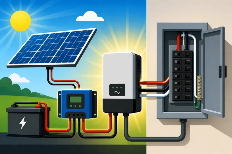
Think of your inverter as the translator for your off-grid system. Solar panels and batteries produce Direct Current (DC) power – the kind of electricity you find in car batteries or flashlights. Most of our household appliances, however, run on Alternating Current (AC) power, which is what comes out of the wall outlets in a grid-tied home. The inverter's job is to take that DC power from your batteries and convert it into usable AC power. Without it, you'd be limited to only running 12V or 24V DC appliances, which seriously curtails your modern conveniences.
There are different types of inverters, like pure sine wave, modified sine wave, and even inverter-chargers. A pure sine wave inverter is generally recommended for off-grid living because it produces a clean, consistent waveform that's safe for all electronics, from sensitive medical equipment to your refrigerator. Modified sine wave inverters are cheaper but can cause issues with certain appliances and lead to buzzing or overheating. Some inverters, often called inverter-chargers, also have the ability to charge your batteries from an AC source like a generator or shore power, which can be incredibly handy for backup. When you're making your selection, it's worth diving deeper into how to choose an off-grid inverter to ensure it meets your specific needs. Understanding your inverter's specifications, like its continuous power output, surge rating, and input voltage range, is paramount to a successful connection.
Your Battery Bank: The Energy Reservoir
If the inverter is the translator, your battery bank is undeniably the heart of your off-grid system, the crucial storage unit that allows you to use power even when the sun isn't shining. The most common battery types for off-grid applications are lead-acid (like flooded or AGM) and lithium-ion (specifically LiFePO4). While lead-acid batteries are often more budget-friendly upfront, LiFePO4 batteries offer significantly longer lifespans, deeper discharge capabilities, and require less maintenance, making them a popular choice for serious off-gridders. You can learn more about the Best Off-Grid Solar Batteries to decide which type is best for you.
When you're looking at your battery bank, you'll notice terminals – typically positive (+) and negative (-). These are where your cables will connect. It's critical to know your battery bank's nominal voltage (e.g., 12V, 24V, or 48V), as this must match the input voltage requirements of your inverter. Building a battery bank often involves connecting multiple batteries in series, parallel, or a combination of both to achieve the desired voltage and capacity. This wiring is a whole process in itself, and understanding how to wire a battery bank is fundamental before connecting other components. The size of your battery bank, measured in Amp-hours (Ah) or Kilowatt-hours (kWh), directly determines how long you can power your home without solar input.
Essential Safety Devices and Tools
Safety cannot be overstated when working with electricity, especially high-current DC systems. Before you even think about connecting anything, gather your safety gear. This isn't just a suggestion; it's a critical step that could prevent serious injury or damage to your equipment.
First up, you'll need proper Personal Protective Equipment (PPE). This includes heavy-duty insulated gloves to protect against electrical shock, safety glasses to shield your eyes from sparks, and possibly even an arc-flash suit for larger systems. You'll also need the right tools: a good quality multimeter for testing voltage and continuity, a wire stripper/crimper for preparing cables and attaching lugs, and a set of insulated wrenches and screwdrivers. Crucially, you'll need appropriate DC circuit protection. This means a main DC disconnect switch, often a large knife-style switch, positioned between your battery bank and your inverter. This allows you to completely isolate the inverter from the batteries for maintenance or in an emergency. Additionally, properly sized fuses or DC circuit breakers are absolutely essential to protect your inverter and batteries from overcurrents and short circuits. These are typically installed on the positive cable run close to the battery bank. Understanding how to size fuses and breakers is paramount to prevent catastrophic failures. You can often find many of these tools and safety components, like heavy-gauge cables and disconnects, through reputable online retailers like Renogy or by searching on Amazon.
Safety First: Non-Negotiable Preparations Before Wiring
Alright, you've got your components, you've got your tools, and you understand the basics. Now, let's get serious about safety. Skipping these preparatory steps is like deciding to learn to swim by jumping into the deep end with concrete shoes on. It might seem like a shortcut, but it will end badly. Taking the time to properly prepare your workspace and your system ensures a smooth, safe, and successful connection.
Power Down: Isolating All Energy Sources
This is the golden rule of electrical work: always assume wires are live until you've proven otherwise, and then disconnect them anyway. Before you connect your inverter to your batteries, every single component that could supply power to your battery bank must be turned off and disconnected.
First, go to your solar charge controller and cover your solar panels, or use your PV disconnect switch to entirely cut off the flow of electricity from the solar array. This prevents your panels from sending power to your batteries while you're working. Next, if you have any other charging sources, like a backup generator or a shore power connection, ensure they are also disconnected or turned off at their source. Finally, and this is crucial, disconnect any loads that might be drawing power from your battery bank. If your existing DC distribution panel is connected, switch off all circuit breakers or pull fuses. The goal here is to ensure that your battery bank is the only live component in the immediate vicinity, and even then, we'll treat it with utmost respect. For a deeper dive into the overall safety aspects, reviewing Off-Grid Solar Safety and Grounding is highly recommended.
Personal Protection and Securing Your Workspace
You've already gathered your PPE, now put it on! Those insulated gloves and safety glasses aren't just for show; they're your primary line of defense. When working with batteries, especially lead-acid, there's a risk of corrosive acid spills or explosive gasses, so having baking soda nearby to neutralize acid is a good idea. Even with sealed lithium batteries, there's always an electrical hazard.
Beyond personal protection, securing your workspace is key. Ensure the area is well-lit and free of clutter. Remove any metallic objects from your person, such as rings, watches, or necklaces, as these can create dangerous short circuits if they accidentally touch terminals. Make sure the floor is dry and non-conductive. If you're working with multiple batteries, consider using terminal covers to prevent accidental contact with live terminals you're not currently working on. It's also wise to have a fire extinguisher rated for electrical fires (Class C) readily accessible. A clear head and a methodical approach will significantly reduce risks.
Matching Voltages: Inverter and Battery Bank Harmony
One of the quickest ways to damage your expensive equipment (and yourself) is to mismatch voltages. Your inverter has a specific DC input voltage range, and your battery bank must supply voltage within that range. If your inverter is designed for a 48V battery bank, connecting it to a 12V or 24V bank will simply not work, and could permanently damage the inverter. Conversely, trying to connect a 48V battery bank to a 12V inverter is an express ticket to fried electronics and potential fire.
Before making any connections, use your multimeter to carefully measure the voltage across your battery bank's main positive and negative terminals. Ensure this reading closely matches the nominal input voltage specified on your inverter. If you're working with a battery bank composed of multiple batteries, double-check that you've wired them correctly to achieve the desired system voltage. For example, connecting four 12V batteries in series will give you a 48V bank, whereas connecting them in parallel will keep them at 12V but increase capacity. This choice of 12V vs 24V vs 48V: Which to Choose has significant implications for system design and cable sizing. This verification step is non-negotiable and must be done every single time you connect or reconfigure parts of your system.
The Connection Blueprint: Step-by-Step Wiring
With all safety checks done and your workspace prepared, we're finally ready to make the physical connections. This part requires precision and patience. Rushing through it is a recipe for mistakes. Remember, we’re dealing with high-current DC, so even a momentary slip can be very dramatic. Take your time, follow these steps, and double-check everything as you go.
Making the Initial Battery Connections
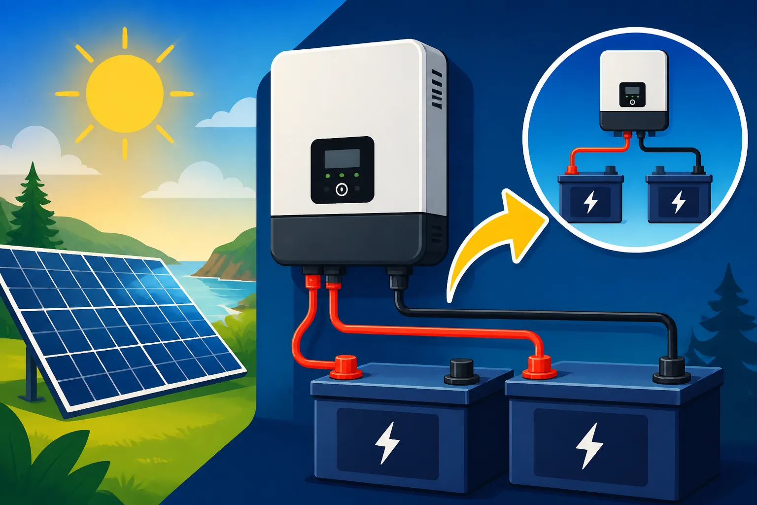
The first physical connection involves your main DC cables to the battery bank. You'll have two large, heavy-gauge cables: one for positive (typically red) and one for negative (typically black). These cables will run from your battery bank to your inverter's DC input terminals.
Before attaching the cables, ensure you have correctly sized and crimped terminal lugs on both ends of your cables. If you're not confident in your crimping skills, it might be worth purchasing pre-made cables with factory-crimped lugs. For connecting to the battery bank, identify the main positive and negative terminals. These are usually the points where all individual battery connections ultimately terminate if you have a multi-battery bank. Connect the negative cable first to the negative terminal of your battery bank. Secure it tightly with the appropriate wrench, but don't overtighten and strip the bolt. Once the negative is secure, and only then, connect the positive cable to the positive terminal of your battery bank. Again, tighten securely. After both cables are connected to the battery, you might want to consider putting terminal covers on them to prevent accidental contact, especially if you're working with exposed terminals. This is a critical step in the broader process of how to wire an off-grid solar system.
Attaching Cables to Your Inverter
Now, with your battery cables securely connected to the battery bank (and the other ends still unconnected to anything, hanging free), it's time to route them to your inverter. Your inverter will have clearly marked DC input terminals – usually large studs or screw terminals labeled (+) and (-).
First, and this is crucial for safety, make sure your DC disconnect switch (if you have one installed) is in the "OFF" position or that the fuses are not yet inserted. If you’re not using a dedicated DC disconnect, ensure the ends of your battery cables that will connect to the inverter are isolated and cannot accidentally touch each other or the inverter casing. Now, connect the negative cable (black) to the inverter's negative DC input terminal. Tighten it firmly. Next, connect the positive cable (red) to the inverter's positive DC input terminal. Ensure both connections are snug and secure. Loose connections are a common cause of arcing, heat buildup, and system failures. Give each cable a gentle tug to confirm it's seated properly. If you've got an inverter-charger, like many popular models from Renogy, it might have additional AC input/output terminals, but for this specific step, we are only focusing on the DC battery connection.
Double-Checking and Bringing Your System to Life
You're almost there! Before applying power, perform a thorough visual inspection. Trace the positive cable from the battery bank to the inverter. Then trace the negative cable. Confirm that positive connects to positive, and negative connects to negative. This reverse polarity check is absolutely vital. A mistake here will almost certainly damage your inverter, and could pose a fire hazard. Ensure there are no stray wire strands, no tools left on battery terminals, and all connections are tight.
Once you are absolutely confident that everything is correctly wired and secure, you can proceed to energize the system. If you have a main DC disconnect switch, slowly flip it to the "ON" position. If you are using fuses, carefully insert the fuses into their holders. Pay close attention to your inverter. It should typically emit a beep or click and its display should light up, indicating it has power. Many inverters go through a self-test sequence. Consult your inverter's manual for specific start-up procedures and expected indicators. If you hear unexpected noises, smell anything burning, or see smoke, immediately disconnect power at the battery disconnect. It's a good idea to monitor the inverter for a few minutes to ensure it's operating normally before connecting any AC loads. You've successfully completed a major milestone in your DIY off-grid setup!
Selecting the Right Connectors: Cables, Lugs, and Fuses
The unsung heroes of any off-grid solar system are the cables, lugs, and fuses. These aren't components you want to skimp on. Using undersized cables can lead to dangerous overheating and voltage drop, while incorrect fuses leave your valuable equipment vulnerable. Investing a little more here means a safer, more efficient, and more reliable system in the long run.
Choosing the Correct Wire Gauge for DC Currents
When we talk about wire gauge, we're referring to the thickness of the wire. The American Wire Gauge (AWG) system is commonly used, where a lower AWG number indicates a thicker wire. For example, 4/0 AWG (pronounced "four aught") is much thicker than 6 AWG. Why does thickness matter? Because DC currents, especially the high currents flowing between your battery bank and inverter, can generate a lot of heat in thin wires and cause significant voltage drop over distance. Voltage drop means your inverter isn't getting the full voltage it expects, which can reduce efficiency and even lead to system shutdowns.
To select the right gauge, you need to consider two main factors: the maximum current your inverter will draw from the batteries and the length of the cable run. The inverter's maximum continuous power rating divided by your battery voltage will give you the maximum current (Amps). For instance, a 3000W inverter running on a 12V battery bank will draw up to 250 Amps (3000W / 12V). This is a substantial current! Always err on the side of caution and go for a thicker gauge if you're between sizes. You can find detailed charts and calculators online that help you determine the appropriate wire gauge based on current and distance, often linked in guides like how to size wire and cables.
Here's a simplified reference table for typical applications, but always consult specific wire gauge charts for your exact system:
| System Voltage | Inverter Size (Continuous) | Approximate Max Amps | Recommended AWG (up to 5 ft) | Recommended AWG (5-10 ft) |
|---|---|---|---|---|
| 12V | 1000W | 83A | 2 AWG | 1/0 AWG |
| 12V | 2000W | 167A | 2/0 AWG | 4/0 AWG |
| 24V | 2000W | 83A | 2 AWG | 1/0 AWG |
| 24V | 3000W | 125A | 1/0 AWG | 2/0 AWG |
| 48V | 3000W | 63A | 4 AWG | 2 AWG |
| 48V | 5000W | 104A | 1/0 AWG | 2/0 AWG |
Note: This table provides general guidance. Always cross-reference with professional resources and consider surge currents and specific cable insulation ratings. Shorter runs are always better for minimizing voltage drop.
Fuses, Breakers, and Disconnects: Your System’s Guardians
Just like a fuse box protects your home's wiring from overloads, your off-grid system needs robust protection between the battery bank and the inverter. This typically comes in the form of a large DC rated fuse or a DC circuit breaker, accompanied by a heavy-duty disconnect switch. The primary purpose of these devices is to protect the wiring and the inverter from excessive current draw in case of a fault (like a short circuit) or an overload.
The fuse or breaker rating must be carefully chosen. It should be sized slightly above the maximum continuous current that your inverter will draw but below the maximum current rating of your cables. If the fuse is too small, it will blow prematurely under normal operation or during inverter surge loads. If it's too large, it won't protect your equipment in an overload situation. Again, the inverter's manual will often provide a recommended fuse size. A good rule of thumb is to size the fuse at 125% of the continuous current rating of the inverter's input. For example, if your 12V inverter draws a maximum of 250A, you might size your fuse around 300-350A. A knife disconnect switch, such as those available from brands like Renogy or through various vendors on Amazon, provides a safe, visible way to physically break the circuit for maintenance or emergencies. It’s a literal lifeline for your system.
Crimping Lugs: Ensuring Solid Electrical Contacts
The connection points are often the weakest links in any electrical system. This is where terminal lugs come in. Lugs are metal connectors, usually copper, that are crimped onto the end of your large gauge cables. These provide a clean, secure, and conductive surface for bolting to your battery terminals and inverter posts.
Proper crimping is an art and a science. A poor crimp creates high resistance, which leads to heat buildup, power loss, and potential fire hazards. You absolutely need a high-quality crimping tool, often called a hydraulic crimper or a hammer crimper, for these large gauge wires. Regular pliers won't cut it. To make a proper crimp, strip about an inch of insulation from the cable, insert the bare copper strands fully into the lug barrel, and then use your crimper to compress the barrel tightly onto the wire. It should be so tight that the cable cannot be pulled out of the lug. Some lugs are designed to be soldered, but a proper mechanical crimp is generally preferred for high-current DC applications due to vibration and heat expansion concerns. After crimping, it's a good practice to use heat-shrink tubing over the crimped area and part of the lug to provide insulation and strain relief, protecting against corrosion and accidental shorts.
Troubleshooting Common Connection Challenges
Even with the best preparation, sometimes things don't go exactly as planned. Don't panic! Troubleshooting is a natural part of any DIY project, especially with something as complex as off-grid solar. Knowing how to identify and address common issues can save you a lot of frustration and potential equipment damage.
Avoiding Reverse Polarity and Loose Connections
These two issues are perhaps the most common, and potentially damaging, mistakes when connecting an inverter to batteries.
Reverse Polarity: Connecting the positive battery cable to the negative inverter terminal, and vice-versa, is what's known as reverse polarity. In some systems, this can instantly destroy your inverter. Modern inverters often have some level of reverse polarity protection, but it's never something you want to rely on. The damage can range from blowing internal fuses (which may or may not be user-serviceable) to permanently frying internal components. The best way to avoid this is diligent, repeated visual inspection before applying power. Always double-check: Red to Positive, Black to Negative. Use a multimeter to confirm polarity on your battery bank if you're ever unsure about which terminal is which. The simple act of tracing each cable from one end to the other, twice, will often catch this critical error.
Loose Connections: A loose connection isn't just annoying; it's a serious safety hazard. High currents passing through a high-resistance point (like a loose cable lug) generate significant heat. This heat can melt insulation, damage terminals, and even cause fires. You might notice flickering lights, inconsistent power output from your inverter, or even a burning smell. To prevent this, ensure all bolts are tightened firmly with the appropriate tools. Don't just finger-tighten; use a wrench. However, don't overtighten either, as you could strip threads or crack plastic terminals. After running your system for a short period (say, an hour or two), it's a good practice to carefully re-check all high-current connections for warmth. If a connection feels excessively hot to the touch, it's likely loose or poorly made, and you need to power down and investigate immediately. This attention to detail is crucial for ensuring a reliable setup, as detailed in guides on how to install an off-grid solar system.
Dealing with Overcurrent and Short Circuits
Overcurrents and short circuits are serious threats to your off-grid system, but that's exactly why we install fuses and breakers!
Overcurrent: An overcurrent situation occurs when too much current is drawn through a circuit. This could happen if you try to run too many appliances simultaneously, exceeding your inverter's continuous power rating or surge capacity. While fuses and breakers are designed to trip or blow in these scenarios, repeated overcurrents indicate an undersized system or an appliance problem. If your fuse blows or breaker trips, don't just replace it and hope for the best. First, identify what caused the overcurrent. Was it a specific appliance? Was your inverter trying to start a high-surge motor like a well pump or a mini split? Review your energy usage and your inverter's specifications. You might need to adjust your habits, upgrade your inverter, or consider adding a soft-start device to high-draw appliances. Remember, a larger fuse or breaker is not the answer to persistent overcurrents; it just bypasses the protection and could lead to system damage.
Short Circuits: A short circuit is an electrical circuit that allows current to travel along an unintended, low-resistance path. This usually happens when a positive wire accidentally touches a negative wire, or a live wire touches a grounded metal component. The current flow during a short circuit can be incredibly high and instantaneous, generating immense heat and sparks. This is where your fuses and breakers are lifesavers. They are designed to detect this sudden, massive surge of current and immediately break the circuit. If a fuse blows or a breaker trips due to a short circuit, never reset or replace it until you have found and fixed the short. Inspect all wiring for damaged insulation, pinched wires, or accidental contact points. Use your multimeter to check for continuity between positive and negative lines (with all power off, of course). A short circuit can damage equipment, start fires, and cause serious injury.
Decoding Inverter Alarms and Error Messages
Modern off-grid inverters are sophisticated pieces of equipment, often equipped with microprocessors and diagnostic capabilities. When something isn't quite right, your inverter will frequently try to tell you about it through audible alarms (beeps, buzzes) or error codes displayed on its screen. Don't ignore these! They are invaluable clues to what's going on.
Every inverter model has its own specific set of error codes, so the very first thing you should do when you encounter an alarm or error is to consult your inverter's manual. Seriously, keep that manual handy! Common error messages might include "Low Battery Voltage," "Overload," "Over Temperature," "Input Over-Voltage," "Short Circuit," or "Internal Fault." A "Low Battery Voltage" alarm means your battery bank is too depleted to safely supply power, indicating you need more solar input, a larger battery bank, or reduced consumption. An "Overload" typically means you're trying to draw more power than the inverter can provide. "Over Temperature" suggests insufficient ventilation or high ambient temperatures, causing the inverter to overheat. When you see an error code, note it down, look it up in your manual, and follow the recommended troubleshooting steps. Often, these steps involve disconnecting loads, checking connections, or allowing the system to cool down. Brands like Victron Energy and Outback Power are known for their comprehensive diagnostic systems, which, while complex, provide a lot of insight into system health.
Disclaimer
Please remember that working with electricity, especially high-voltage DC systems, can be dangerous and potentially life-threatening. This guide provides general information and best practices. Always consult certified electricians or solar professionals for advice specific to your setup and local electrical codes. Incorrect installation or wiring can lead to property damage, severe injury, or even death. Proceed with caution and at your own risk.