How to Connect Multiple Solar Panels
Stepping into the world of off-grid solar can feel like learning a whole new language, especially when you start thinking about how to get multiple solar panels talking to each other. Many folks find themselves scratching their heads, wondering if they should connect them in series, parallel, or some kind of mix, all while worrying about frying their system or not generating enough power. This comprehensive guide is here to untangle that confusion, walking you through the ins and outs of connecting multiple solar panels to build a robust and efficient off-grid power system.
Deciphering the Basics: Series vs. Parallel Panel Wiring
Before you even think about grabbing your tools, it's absolutely crucial to understand the fundamental ways solar panels can be connected: series, parallel, or a combination of both. Each method has distinct implications for your system's voltage, current, and overall performance, and choosing the right one is the first big step in your solar journey.
The Ins and Outs of Series Connections
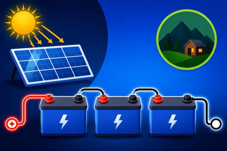
Imagine a train with multiple cars, where the positive terminal of one panel connects directly to the negative terminal of the next. That's essentially series wiring. When you connect solar panels in series, their voltages add up, while the current (amperage) remains the same as that of a single panel. So, if you have three 12-volt panels, each producing 5 amps, wired in series, your output will be 36 volts and still 5 amps.
This method is particularly useful for systems that require higher voltages, such as 24V or 48V battery banks. Higher voltage systems generally lead to less current, which in turn means you can use smaller gauge wiring over longer distances without significant power loss due to voltage drop. This can save you money on thicker, more expensive cables. However, a significant drawback of series wiring is that if one panel in the string experiences shading or malfunction, the entire string's output can be reduced or even halted, much like an old string of Christmas lights where one bulb going out kills the whole string. It's a common mistake to overlook this when planning your Off-Grid Solar System Sizing Guide or considering how many solar panels for off-grid living, especially if your installation site has potential for partial shading throughout the day.
Unpacking Parallel Connections
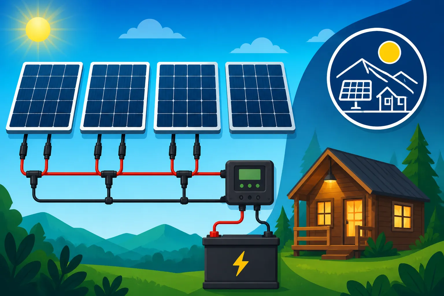
Now, picture a river splitting into several streams and then rejoining further downstream. Parallel wiring is similar, connecting all positive terminals together and all negative terminals together. In this setup, the current (amperage) from each panel adds up, while the voltage remains the same as that of a single panel. Using our previous example of three 12-volt, 5-amp panels, wired in parallel, your output would be 12 volts and a combined 15 amps.
Parallel connections are excellent for maintaining a lower system voltage while increasing the overall current, which is often desirable for 12V RV or boat systems where many appliances run directly on 12V DC. A significant advantage is redundancy: if one panel is shaded or fails, the other panels in the array continue to produce power unimpeded, only reducing the total current output. This resilience makes parallel connections a favorite for setups where reliable power is paramount and consistent sunlight across all panels might not always be guaranteed. However, the higher current generated in parallel systems means you'll need thicker gauge wiring to prevent voltage drop, especially over longer runs, which can add to your Cost of Off-Grid Solar Panels and overall setup.
Combining the Best: Series-Parallel Arrangements
For many off-grid homeowners, RV dwellers, and cabin owners, a hybrid approach of series-parallel wiring offers the best of both worlds. This method involves connecting groups of panels in series to form "strings" and then connecting those strings together in parallel. For instance, you might have two strings of two panels each. If each panel is 12V/5A, a series string would be 24V/5A. Connecting two of these 24V/5A strings in parallel would result in a final output of 24V/10A.
This configuration is incredibly versatile and allows you to optimize your system for both voltage and current requirements. It’s particularly beneficial for larger arrays where you need to reach a specific higher voltage (e.g., 48V for a whole-house system) while still providing some protection against partial shading. For example, if one panel in one series string is shaded, only that string's output is affected, not the entire array. This makes it a popular choice for those looking to maximize efficiency and reliability without incurring excessive costs for super thick wiring or extremely powerful individual components. When learning how to size an off-grid inverter or how to size a charge controller, understanding your series-parallel configuration will be key.
Gathering Your Gear and Prepping for Success
Before you start connecting anything, proper preparation is non-negotiable. Having the right tools, materials, and a clear understanding of your system's requirements will not only ensure a smoother installation but also guarantee the safety and longevity of your off-grid solar setup.
Essential Tools and Safety Equipment
Working with electricity, even low-voltage DC from solar panels, demands respect and proper safety gear. You'll definitely want a high-quality multimeter for checking voltage and continuity at various stages of your installation. Wire strippers and crimpers designed for solar-specific MC4 connectors are crucial for making solid, weatherproof connections. An MC4 disconnect tool will save you a lot of frustration if you ever need to separate connections. Don't forget your personal protective equipment: insulated gloves, safety glasses, and non-slip boots are not optional.
Beyond basic tools, having a robust solar cable and wire cutter ensures clean, precise cuts. For larger systems, a dedicated torque wrench for tightening terminal connections to specification can prevent loose connections and potential hotspots. Many of these specialized tools, like MC4 crimpers and solar wire, are readily available on platforms like Amazon, making it easier for DIYers to get started.
Selecting the Right Cables and Connectors
The cables and connectors are the arteries and veins of your solar system. For connecting panels, you'll primarily be using specialized UV-resistant solar PV cable, usually 10 AWG or 12 AWG, terminated with MC4 connectors. These connectors are designed to be waterproof and provide a secure, locking connection. The gauge of your wire is critical and depends on the amount of current it needs to carry and the distance it has to travel. Too thin a wire for the current, and you'll experience excessive voltage drop, which translates to wasted power and reduced system efficiency.
When wiring panels in parallel, you might use MC4 Y-branch connectors to combine multiple panel outputs into a single run to your charge controller. For series connections, the existing leads on your solar panels often suffice, or you might need short extension cables with MC4 connectors. Always opt for good quality, purpose-built solar cables and connectors. A reliable brand like Renogy offers a variety of these essential components, often included in their solar kits, ensuring compatibility and durability. Poor quality connectors are a common source of system failures and safety hazards.
Sizing Your Charge Controller and Inverter for Your Array
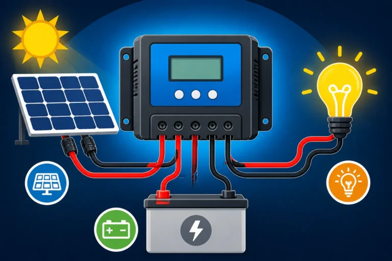
Your solar panel wiring directly impacts the sizing of two critical components: your charge controller and your inverter. The charge controller manages the power flow from your panels to your batteries, preventing overcharging. If you've wired your panels in series for higher voltage, you'll need a charge controller that can handle that higher input voltage (Voc – open-circuit voltage) and convert it efficiently to your battery bank's voltage (e.g., a 48V array charging a 24V battery bank). MPPT (Maximum Power Point Tracking) charge controllers are generally recommended for larger or higher voltage arrays because they are much more efficient at converting power from a high-voltage array to a lower-voltage battery bank. For a deeper dive, check out our guide on How to Choose an Off-Grid Charge Controller.
Similarly, your inverter, which converts your battery's DC power into usable AC power for your appliances, needs to be appropriately sized. While the inverter primarily interacts with your battery bank, the total power output of your solar array dictates how quickly and effectively your batteries can be recharged, influencing the overall autonomy and reliability of your system. You'll want to ensure your inverter can handle the combined wattage of all the AC devices you plan to run simultaneously. You can learn more by reading How to Size an Off-Grid Inverter. Failing to properly size these components based on your chosen panel wiring configuration can lead to inefficiencies, component failure, or simply not enough power.
Step-by-Step Connection Protocols for Your Off-Grid System
Now that you understand the different wiring methods and have all your materials, let's get down to the practical steps of connecting your solar panels. Remember, always work safely and double-check every connection.
Wiring Panels in Series
Connecting panels in series is straightforward, but precision is key.
- Identify Terminals: On most solar panels, you'll find two cables exiting the junction box, one typically ending in a male MC4 connector and the other in a female MC4 connector. The male connector is usually positive (+) and the female connector is negative (-).
- First Connection: Take your first solar panel. Its positive (+) output will be the starting point for your string.
- Connecting Panels: Take the negative (-) output cable from the first panel and connect it to the positive (+) input cable of the second panel. This is where the male MC4 from the first meets the female MC4 of the second, or vice-versa, depending on how your panel cables are configured. You'll hear a reassuring click when they're properly seated.
- Continue the Chain: Repeat this process for all subsequent panels in your series string. The negative output of panel #2 goes to the positive input of panel #3, and so on.
- Final Outputs: After connecting all panels in series, you'll be left with one free positive (+) cable from the very first panel in the string and one free negative (-) cable from the very last panel in the string. These two cables represent the combined high-voltage output of your series string and will typically run to your combiner box or directly to your charge controller.
- Verify: Before proceeding, use your multimeter to check the open-circuit voltage (Voc) of your entire series string. This voltage should be approximately the sum of the Voc of each individual panel. For example, if you have four 12V panels with a 21V Voc each, your string should measure around 84V. This crucial check confirms your series connections are sound. For detailed visuals and explanations, refer to our guide on How to Wire Solar Panels in Series.
Wiring Panels in Parallel
Wiring panels in parallel involves connecting like terminals together, and it usually requires special Y-branch connectors or a combiner box.
- Identify Terminals: Again, identify the positive (+) and negative (-) output cables for each panel.
- Combine Positives: Gather all the positive (+) output cables from your individual panels. Connect them all together using an MC4 Y-branch connector or by routing them into a positive busbar or terminal in a solar combiner box.
- Combine Negatives: Similarly, gather all the negative (-) output cables from your individual panels. Connect them all together using another MC4 Y-branch connector or by routing them into a negative busbar or terminal in a solar combiner box.
- Final Outputs: From these combined positive and negative points (the output of your Y-branches or the main terminals of your combiner box), you'll have one main positive (+) cable and one main negative (-) cable. These will carry the combined higher current at the nominal voltage of a single panel to your charge controller.
- Verify: Use your multimeter to check the open-circuit voltage (Voc) of your parallel array. It should be approximately the same as the Voc of a single panel. Then, check the short-circuit current (Isc) by momentarily connecting the positive and negative leads through the ammeter function of your multimeter (only do this briefly and with appropriate safety measures for small arrays, or with a clamp meter for larger systems). This current should be roughly the sum of the Isc of each individual panel. Our article How to Wire Solar Panels in Parallel offers more specific guidance.
Executing Series-Parallel Combinations
For larger off-grid systems, you'll often utilize a series-parallel arrangement to achieve optimal voltage for your charge controller while minimizing current loss over distances and providing some resilience against shading.
- Form Series Strings: First, create individual series strings, following the steps outlined above. For instance, you might make three strings, each consisting of two 12V panels wired in series, resulting in three separate 24V strings.
- Route to Combiner Box: Once your series strings are formed, run the final positive (+) and negative (-) output cables from each string into a solar combiner box. A combiner box is essentially a weather-rated enclosure that houses the connections for multiple strings, often with built-in fusing for each string.
- Combine Strings in Parallel: Inside the combiner box, you will then connect all the positive leads from your series strings to a common positive busbar, and all the negative leads to a common negative busbar. This effectively connects your series strings in parallel.
- Output to Charge Controller: The combiner box will then have one main positive (+) and one main negative (-) output terminal, which will carry the combined power of your entire series-parallel array to your MPPT charge controller.
- Verify: With your multimeter, measure the open-circuit voltage (Voc) at the output of your combiner box. It should match the voltage of a single series string. For example, if each string is 24V, the combined output should also be 24V. Then, use a DC clamp meter to measure the current of each individual string (if possible) and the total current output. The total current should be the sum of the currents from each active string. This method is often the go-to for How to Wire a 48V Off-Grid System for larger residential setups.
Ensuring Longevity and Safety: Best Practices and Troubleshooting
Connecting multiple solar panels is just the beginning. To ensure your off-grid system runs reliably and safely for years to come, you need to adhere to best practices in grounding, overcurrent protection, and learn how to identify and fix common issues.
Electrical Safety Precautions
Safety is paramount. Always assume all wires are live, even when panels are facedown or covered, as even ambient light can generate voltage. Disconnect all loads and cover your solar panels before making or breaking any connections to prevent arcing and potential injury. Use insulated tools wherever possible.
Proper grounding of your solar array and associated equipment is not just a recommendation; it's an electrical code requirement and a critical safety measure. This protects both your equipment and anyone interacting with the system from electrical shocks due to faults or lightning strikes. Ensure all metal frames of your solar panels and any mounting hardware are properly bonded and connected to an earth ground. Your charge controller, inverter, and battery bank enclosures should also be grounded. Our detailed guide on How to Ground an Off-Grid Solar System provides comprehensive instructions on this vital aspect of installation.
Protecting Your System Components
Beyond grounding, overcurrent protection is essential for protecting your wiring and components from damage due to short circuits or overloads.
- Fuses and Circuit Breakers: Install appropriately sized fuses or DC-rated circuit breakers on the positive line of each solar panel string if you're using a combiner box. This way, if one string develops a fault, it doesn't take down the entire system or overload other components. You'll also need a main DC circuit breaker between your charge controller and battery bank, and typically AC circuit breakers between your inverter and your AC load panel.
- Disconnects: A dedicated PV array disconnect switch (DC disconnect) should be installed between your solar array and your charge controller. This allows you to completely isolate the solar panels for maintenance or in case of an emergency without having to disconnect individual wires at the panels. Similarly, a battery disconnect switch between your battery bank and your inverter/charge controller is crucial.
- Surge Protection: In areas prone to lightning, consider installing DC surge protection devices (SPDs) between your solar array and charge controller, and AC SPDs on your inverter's output. These devices can shunt damaging voltage spikes safely to ground, saving your expensive equipment from irreparable harm.
Testing and Verification
Once everything is connected, don't just flip the switch and hope for the best! Thorough testing is crucial to ensure everything is working as intended and to catch any errors before they become major problems.
- Open Circuit Voltage (Voc): Before connecting to the charge controller, measure the Voc of your entire array (or each string if you have a combiner box). This confirms your series connections are correct.
- Short Circuit Current (Isc): For smaller arrays, you can briefly measure the Isc to verify parallel connections are correct. For larger arrays, use a clamp meter on individual string wires or the main output cable from the combiner box.
- Polarity Check: Always double-check polarity at every connection point before connecting to your charge controller and battery bank. Reversed polarity can cause severe damage to your equipment.
- System Startup: Once satisfied with all checks, connect your array to the charge controller, and then connect the charge controller to your battery bank. Monitor your charge controller's display to ensure it's detecting voltage and current, and that the battery is charging correctly. Pay attention to any error codes.
- Load Testing: Gradually connect your loads and monitor the system performance. A good Off-Grid Solar Battery Bank should show consistent charging and discharging cycles, and your inverter should be able to handle your appliances. Many modern charge controllers and inverters, including those from brands like Victron Energy or EG4, offer comprehensive monitoring apps that can provide real-time data on your system's performance, helping you identify any anomalies.
Troubleshooting Common Connection Issues
Even with the best planning, sometimes things don't go exactly as expected. Don't panic! Many common issues with connecting multiple solar panels have relatively simple solutions.
Low Voltage or Current
If your system isn't producing the expected power, the first place to look is at the panels themselves.
- Shading: This is the most common culprit for reduced output. Even partial shading on one panel in a series string can drastically reduce the output of the entire string. Check for any new obstructions like growing trees, new structures, or even accumulated dirt and leaves. Regular cleaning of your solar panels is a vital part of Off-Grid Solar Maintenance Costs.
- Loose Connections: Over time, connections can loosen, or corrosion can build up. Go back through your MC4 connections, checking that they are securely clicked into place and that wires are firmly crimped. Use your multimeter to check voltage at various points along the array to pinpoint where the drop is occurring.
- Damaged Panels or Diodes: A cracked panel or a faulty bypass diode within a panel's junction box can significantly impact its output. Bypass diodes are designed to allow current to flow around a shaded or damaged cell section, but if they fail, they can block the flow. Visually inspect panels for physical damage and use a multimeter to test individual panels.
- Incorrect Wiring: Double-check your wiring diagram against your physical connections. A panel mistakenly wired in reverse polarity within a series string, or incorrect parallel connections, will cause issues. Reviewing your Off-Grid Solar Wiring Diagram Explained is a great first step.
System Not Charging
If your batteries aren't getting a charge from your solar array, the problem could be upstream from the panels or in the interaction between components.
- Charge Controller Settings: Ensure your charge controller is properly configured for your battery type (e.g., LiFePO4 vs Lead-Acid Battery Cost), voltage, and charging parameters. Incorrect settings are a frequent cause of non-charging issues. Many modern charge controllers require specific programming to optimize charging for different battery chemistries.
- Battery Voltage Too Low: Some charge controllers require a minimum battery voltage to "wake up" and begin charging. If your batteries are deeply discharged, you might need to temporarily use an alternative charging source (like a generator or grid charger) to bring them up to a level where the solar charge controller can recognize them.
- Disconnected Wires: It sounds obvious, but a loose or disconnected cable between your panels and charge controller, or between the charge controller and batteries, can stop the flow of power. Check all terminals and connectors for tightness and continuity.
- Blown Fuses or Tripped Breakers: If a short circuit occurred, a fuse might have blown or a breaker might have tripped. Check all fuses and breakers in your system, including those in the combiner box, on the charge controller output, and at the battery bank. Replace blown fuses with new ones of the exact same rating.
It's helpful to break your system down into sections and test each one individually. Start at the panels, confirm output, then move to the charge controller input, then output, and finally to the battery terminals. This systematic approach will help you isolate the problem.
| Feature | Series Wiring | Parallel Wiring | Series-Parallel Wiring |
|---|---|---|---|
| Voltage Output | Sum of individual panel voltages (e.g., 3 x 12V = 36V) | Same as single panel voltage (e.g., 3 x 12V = 12V) | Sum of series string voltages (e.g., 2 x 24V strings = 24V) |
| Current Output | Same as single panel current (e.g., 3 x 5A = 5A) | Sum of individual panel currents (e.g., 3 x 5A = 15A) | Sum of parallel string currents (e.g., 2 x 5A strings = 10A) |
| Cable Gauge | Can use thinner cables due to higher voltage, lower current. | Requires thicker cables due to higher current, lower voltage. | Moderate cable gauge required, balancing voltage and current. |
| Shading Impact | Significant reduction for entire string if one panel is shaded. | Reduced output only from the shaded panel; others continue producing. | Reduced output only from the affected string; other strings continue producing. |
| Best For | Higher voltage systems (24V, 48V+), longer cable runs, MPPT charge controllers. | Lower voltage systems (12V), shorter cable runs, redundancy. | Larger, more complex systems requiring a balance of voltage, current, and redundancy. |
| Complexity | Simple | Simple, but requires Y-connectors or combiner box for multiple panels | More complex, requires careful planning and combiner box. |
Disclaimer
The information provided in this guide is for educational and informational purposes only and is not intended as professional electrical advice. Working with solar electrical systems can be dangerous. Always consult with a qualified electrician or solar professional before installing or modifying any solar power system. Ensure all installations comply with local electrical codes and regulations.